HYDRAULIC SYSTEM
6-69TX525 Service Manual Rev. 000
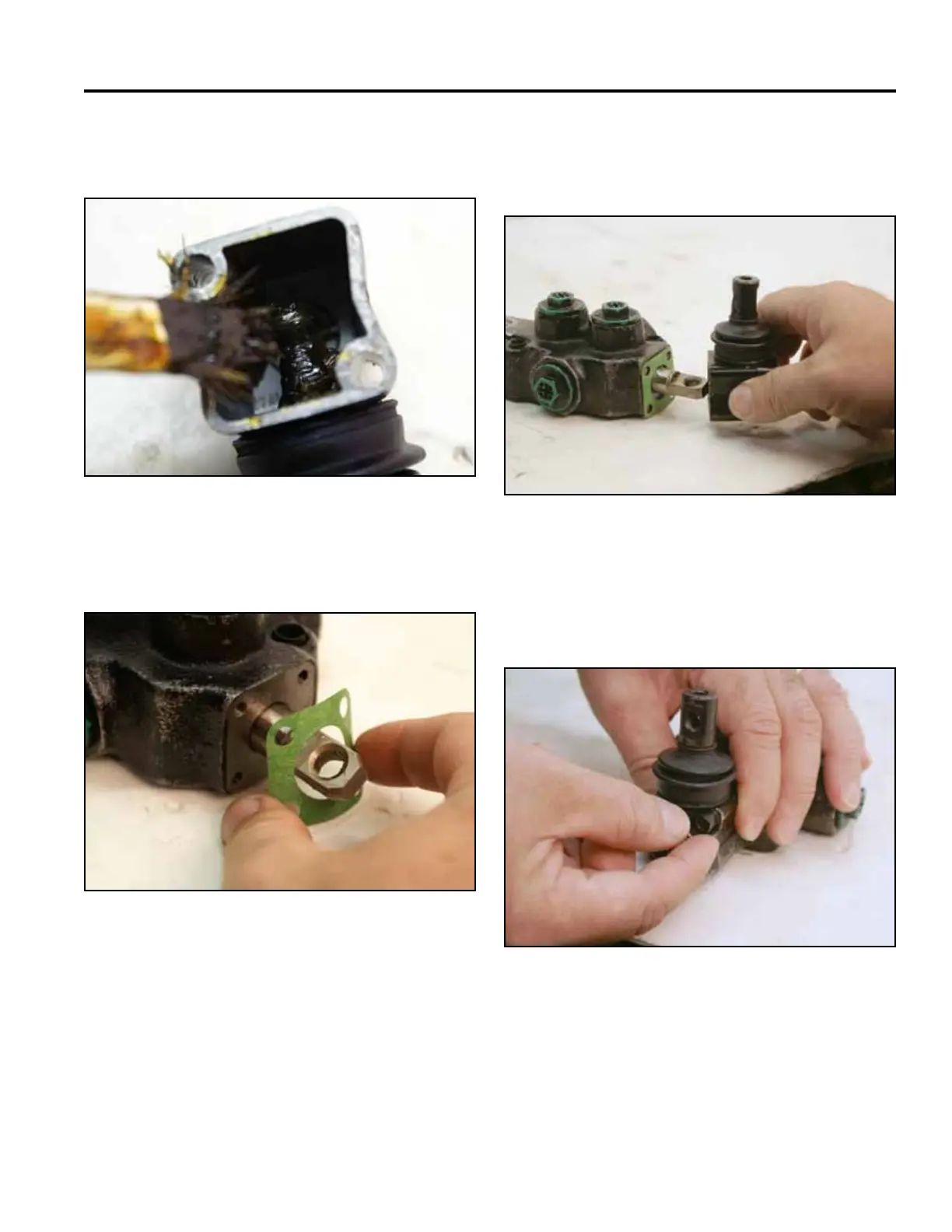
18. Remove the valve from the vise. Grease the swivel
ball in the handle cap (Fig. 1092).
20. Place the handle cap onto the spool gasket. Make
sure the swivel ball in the cap is placed in the open-
ing of the spool (Fig. 1094).
Fig 1092 PICT-2739
Fig 1094 PICT-2741a
21. Install the two bolts to secure the handle cap onto
the valve. Tighten the bolts using a 4mm Allen
wrench (Fig. 1095).
19. Place the gasket onto the valve body (Fig. 1093).
Fig 1095 PICT-2742a
Fig 1093 PICT-2740