HYDRAULIC SYSTEM
6-110 Rev. 000 TX525 Service Manual
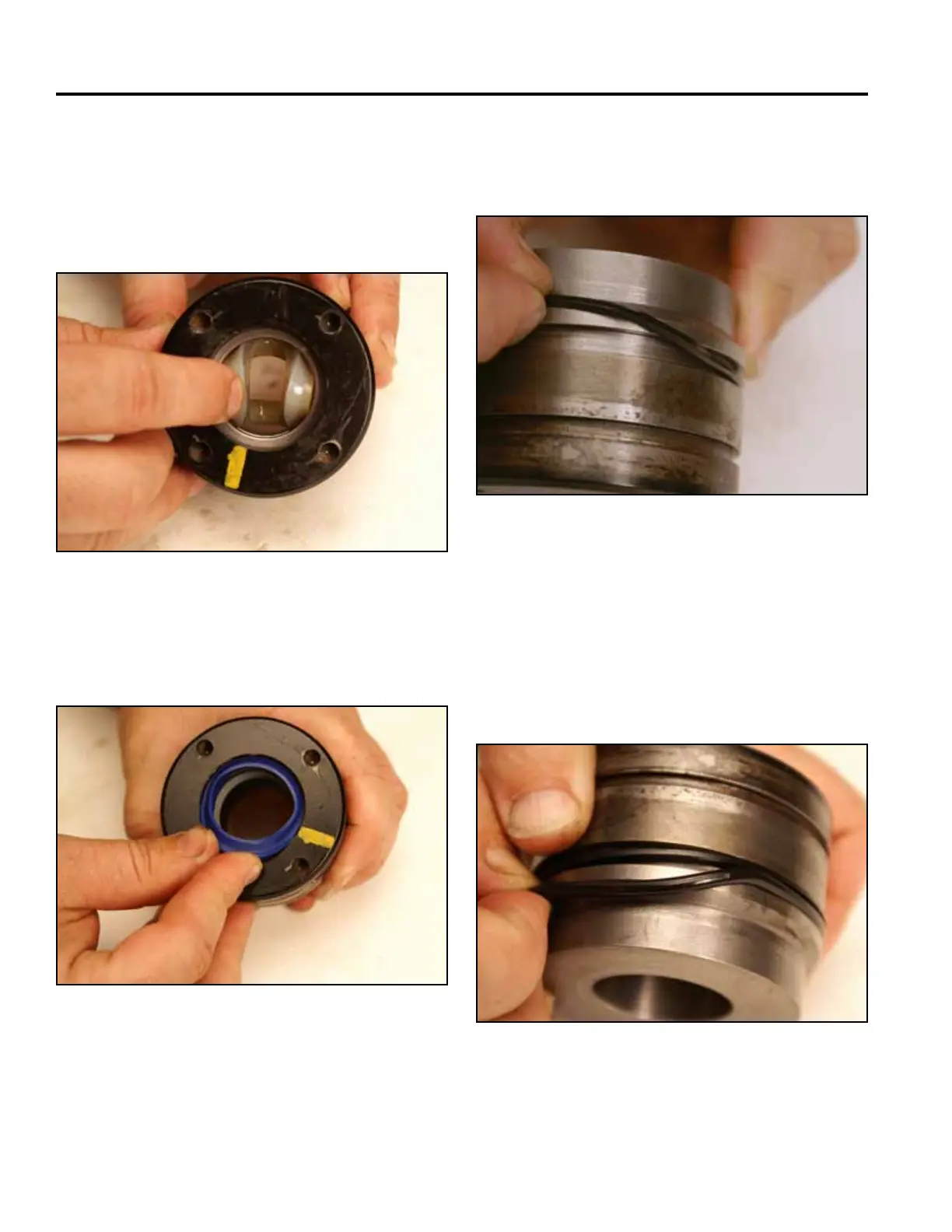
17. Turn the head over and twist the wear seal into a
“C” shape and allow it to snap into the groove (Fig.
1246).
Note: The groove of the seal faces toward the barrel
side of the head.
19. Install the at back-up ring into the deepest groove
in the head. The at back-up seal is installed up
against the ram side of the groove (Fig. 1248).
Fig 1246 PICT-2976
Fig 1248 PICT-2978a
20. Install the o-ring into the deepest groove in the
head. The o-ring is installed on the barrel side of the
groove (Fig. 1249).
Note: If possible, the head/seal assembly should
sit for at least one hour to allow the seals to
normalize.
18. Install the wiper seal so that the lip of the seal is
installed in the groove inside the head (Fig. 1247).
Fig 1249 PICT-2979
Fig 1247 PICT-2977