DRIVE SYSTEM
7-23TX525 Service Manual Rev. 000
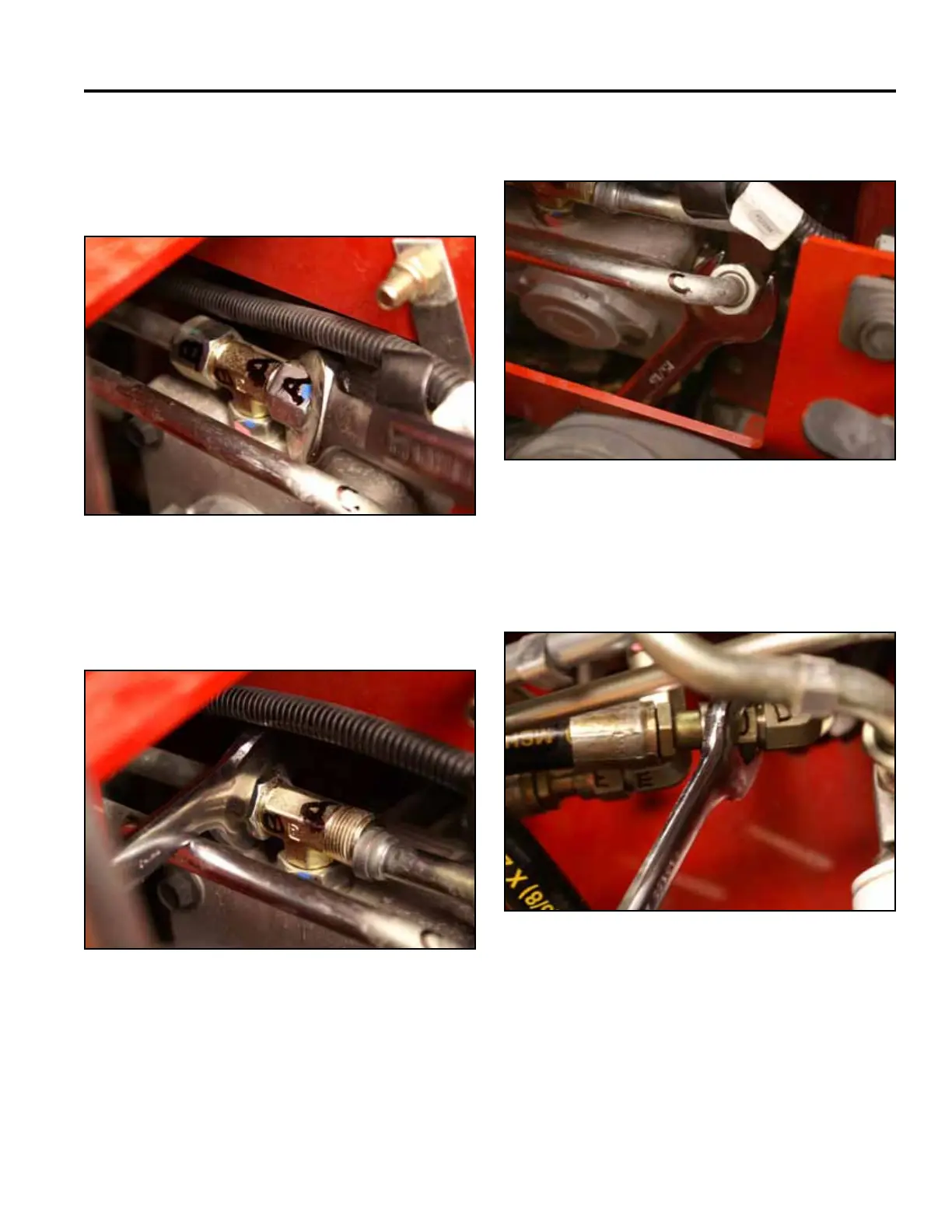
19. Using a 15/16” wrench, disconnect the right hand
hydrostatic pump lines (just marked) as follows:
A. Inletlinefromthehydraulicoillter(Fig.1344).
Fig 1344 PICT-4636
B. Inlet line to the left hand hydrostatic pump (Fig.
1345).
Fig 1345 PICT-4641
C. Case drain line (Fig. 1346).
Fig 1346 PICT-4643a
D. Hydraulic hose running from the “D” port on the
righthandhydrostaticpumptotheuppertting
on the left wheel motor (Fig. 1347).
Fig 1347 PICT-4644