DRIVE SYSTEM
7-25TX525 Service Manual Rev. 000
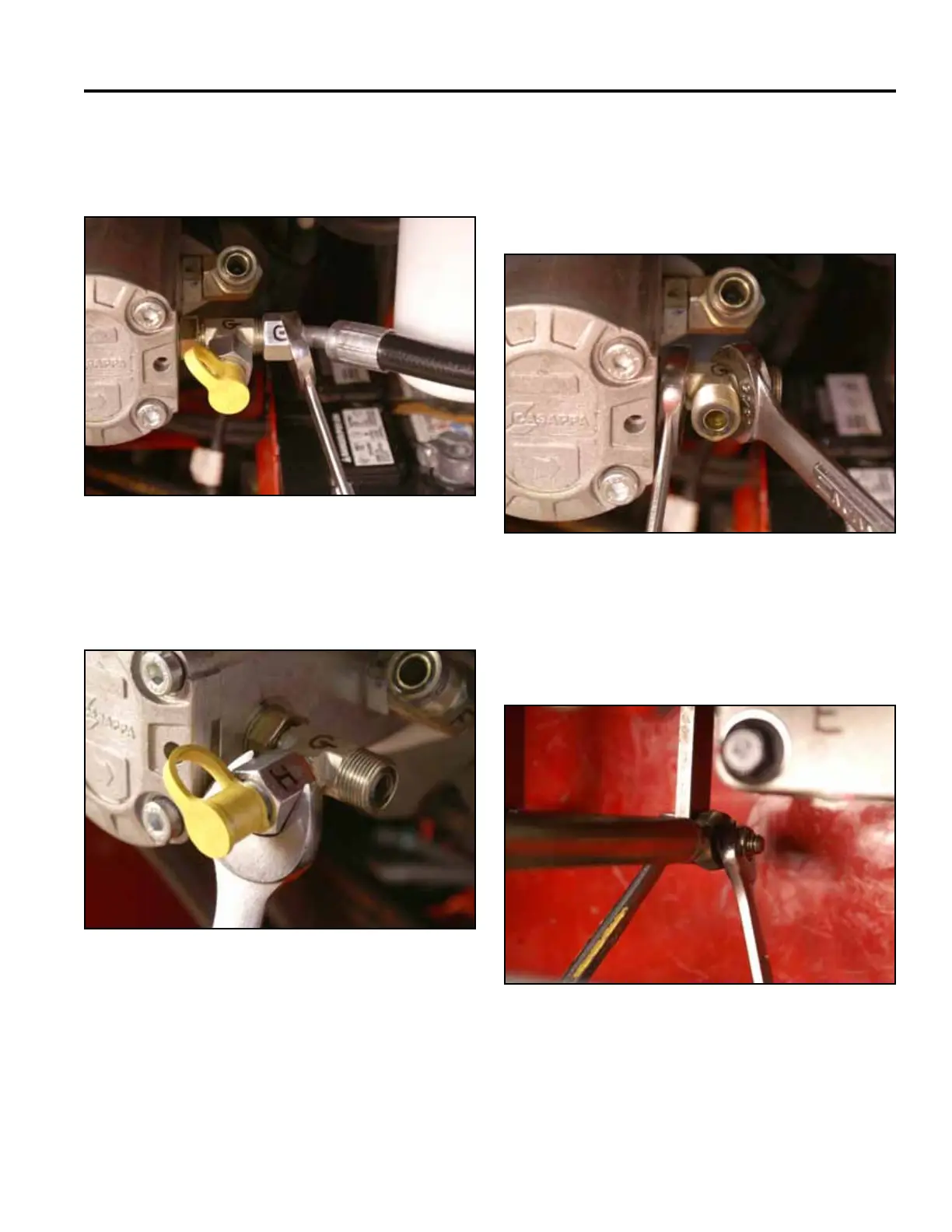
24. Usinga15/16”wrench,removethetestporttting
“H”fromtheT-ttingmarked“G”(Fig.1353).
Fig 1353 PICT-4741a
25. RemovetheT-ttingmarked“G”fromthetandem
pump (Fig. 1354).
Note: Capallhydrauliclinesandttingstoprevent
debris from entering system.
Fig 1354 PICT-4742a
23. Using a 15/16” wrench, remove the hose from the
T-ttingmarked“G”onthetandempump(Fig.
1352).
Fig 1352 PICT-4738a
26. Using a 1/2” socket and wrench, remove the nut and
bolt securing the steering linkage to the right hand
pump control arm (Fig. 1355).
Fig 1355 PICT-4752