DRIVE SYSTEM
7-34 Rev. 000 TX525 Service Manual
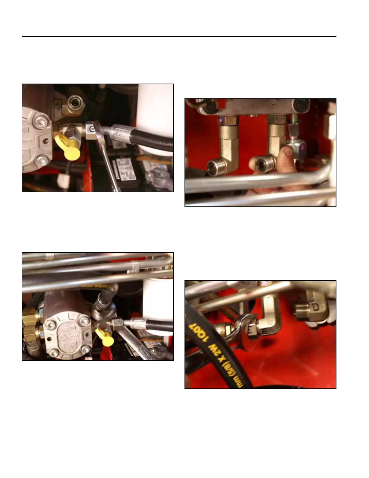
19. Using a 15/16” wrench, install the hose marked “G”
ontotheT-ttingmarked“G”onthetandempump
(Fig. 1388).
Fig 1388 PICT-4738a
20. Using a 1-1/8” wrench, install the hydraulic hose
marked“F”ontothetandempumptting(Fig.1389).
Fig 1389 PICT-4734
21. Looselyinstallthewheelmotorhosettingsmarked
“D” and “E” into the right hand hydraulic pump
ports marked “D” and “E” so they are positioned at
approximately 8:00 (D) and 9:00 (E) clock positions
(Fig. 1390).
Fig 1390 PICT-4755
22. Using a 15/16” wrench, connect the right hand
hydrostatic pump lines as follows:
E. Wheelmotorhosemarked“E”tothetting
marked “E” (Fig. 1391).
Fig 1391 PICT-4645