DRIVE SYSTEM
7-50 Rev. 000 TX525 Service Manual
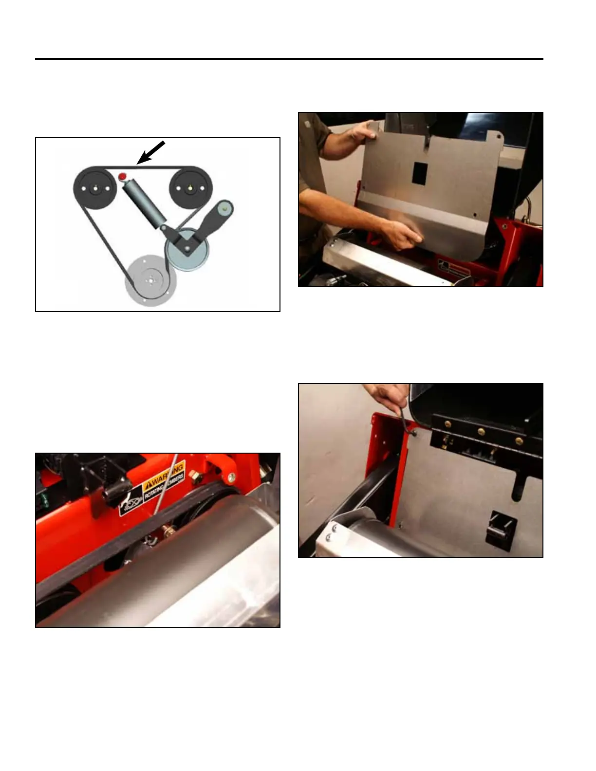
Fig 1451 TX525 belt routing
10. Using a spring tool, install the idler spring onto its
post (Fig. 1452).
A. LH pump pulley D. Idler pulley
B. Drive belt E. Engine pulley
C. RH pump pulley
Fig 1452 Belt 007
9. Route the belt around the engine pulley and the right
and left hydrostatic pump pulleys (rear view) (Fig.
1451).
A C
D
E
B
11. Position the heat shield (Fig. 1453).
Fig 1453 Belt 005
12. Using a 3/16” Allen wrench, install the 2 upper heat
shield screws (Fig. 1454).
Fig 1454 Belt 004