DRIVE SYSTEM
7-51TX525 Service Manual Rev. 000
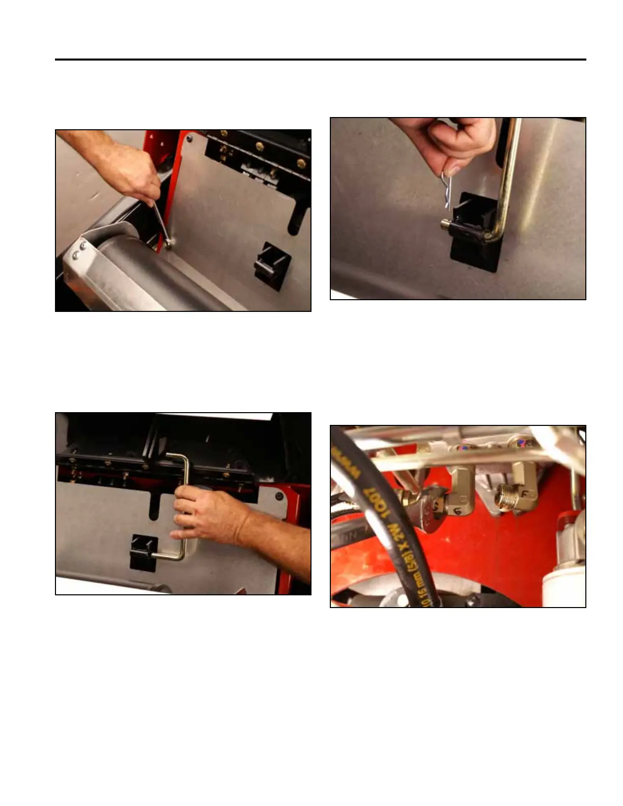
13. Using a 1/2” wrench, install the 2 lower heat shield
screws (Fig. 1455).
Fig 1455 Belt 002
14. Support the hood and install the prop rod (Fig.
1456).
Fig 1456 Belt 003
15. Install the hairpin cotter (Fig. 1457).
Fig 1457 Belt 001
16. Using a 1-1/8” wrench, install the left hand hydro-
static pump lines as follows:
G. Hydraulic hose coming from the upper port on
the left hand wheel motor (Fig. 1458).
Fig 1458 PICT-4623