DRIVE SYSTEM
7-65TX525 Service Manual Rev. 000
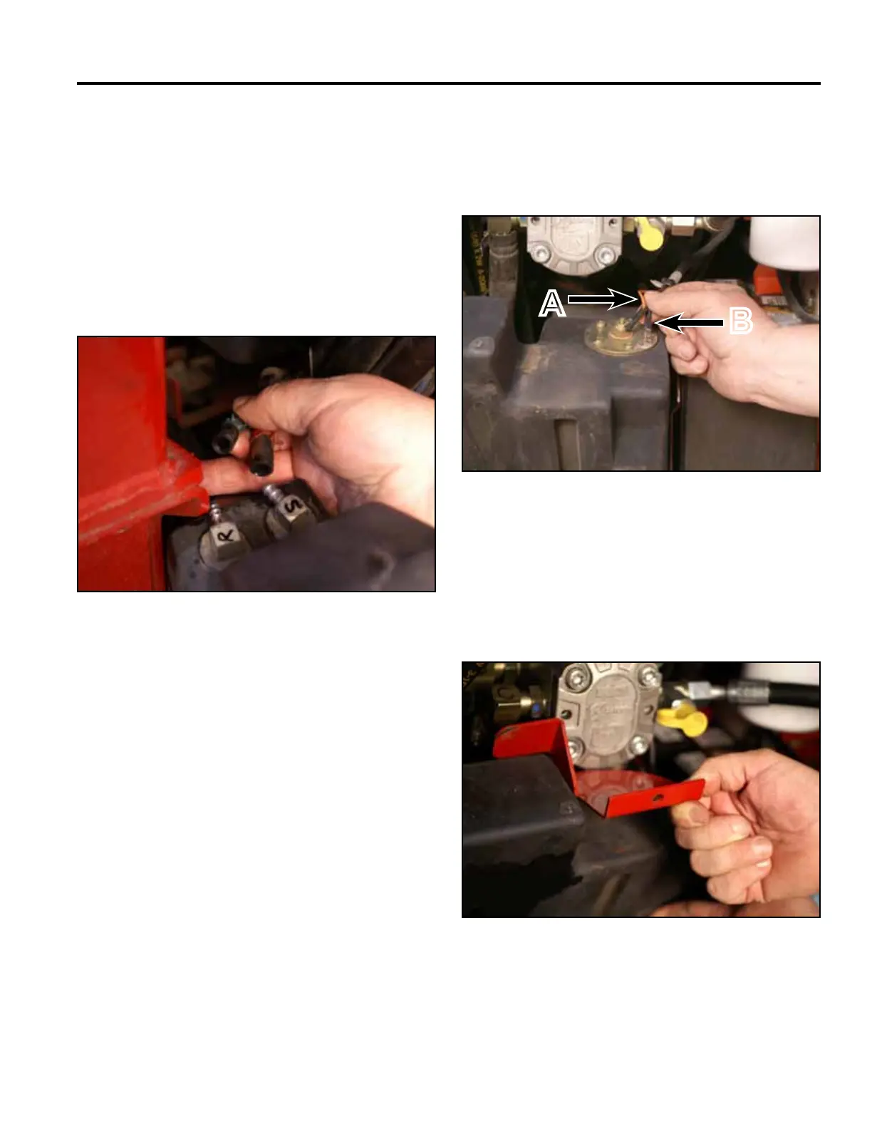
12. Position the fuel tank into the rear end of the frame.
Connect the two wires (black and orange) to the fuel
sending unit located on the top of the fuel tank (Fig.
1508).
Fig 1508 PICT-4262a
13. Position the fuel tank bracket onto the fuel tank (Fig.
1509).
A. Center terminal (orange wire)
B. Outside terminal (black wire)
Fig 1509 PICT-5626
11. Connectthefuellinestothefueltankttings.Note
the location markings. Secure the fuel lines with
hose clamps (Fig. 1507).
S - Fuel suction line
R - Fuel return line
Note: Before installing the fuel tank in the unit,
disengage the park brake and start the unit.
Refer to “Purging Air Procedure” on page
9-19. Check for any leaks in the hydraulic
ttingsandhydraulichoses.
Fig 1507 PICT-4265
A
B