BRAKES
8-4 Rev. 000 TX525 Service Manual
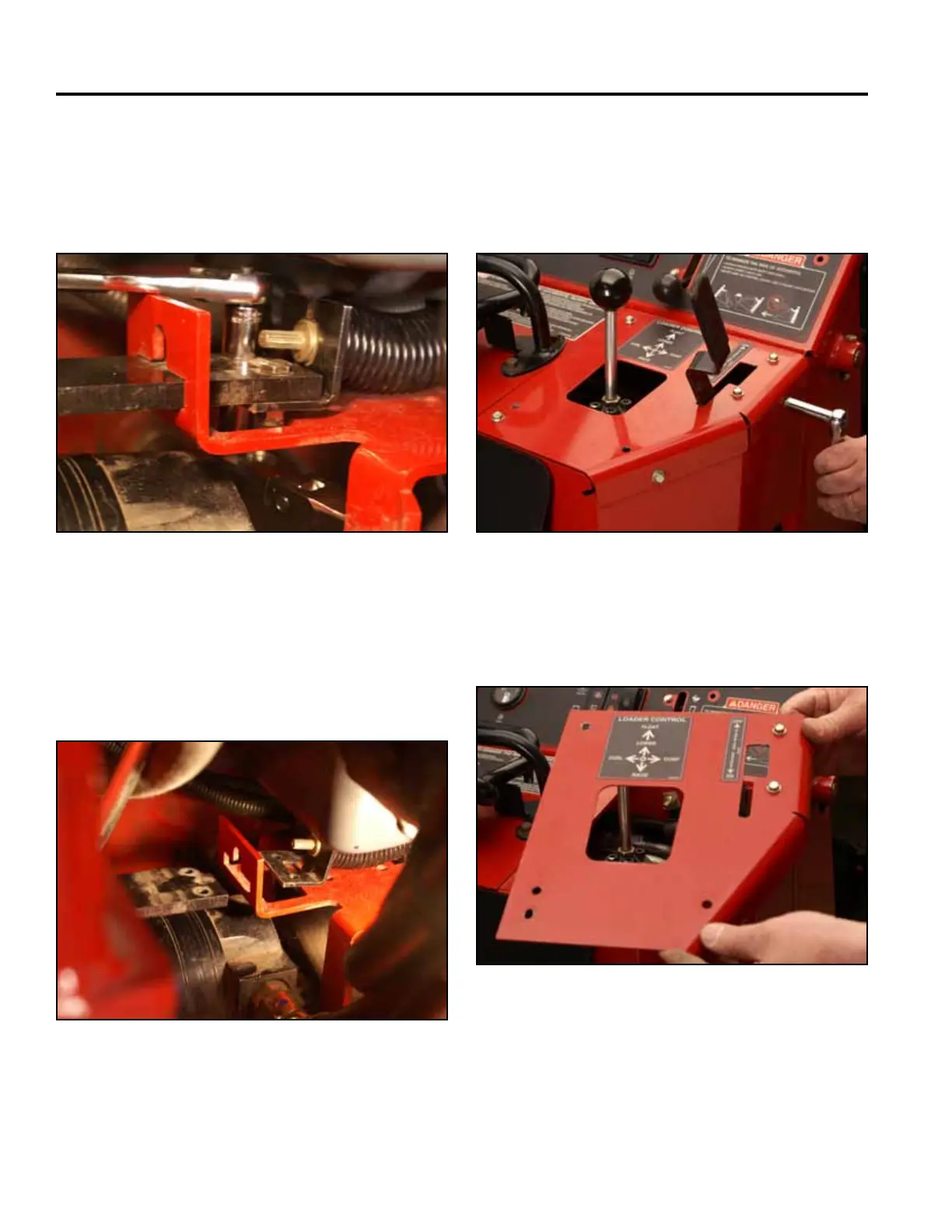
14. Using two 7/16” sockets, remove the 2 bolts and
nuts holding the left hand brake plate to the brake
mounting bracket (the socket/ratchet on the bolt
head should be 1/4” drive to clear the oil pan) (Fig.
1646).
Fig 1646 PICT-4325
15. Push the 2 brake plates outward toward the drive
wheels (Fig. 1647).
Note: The drive wheels may have to rotate to permit
the brake plates to extend fully outward.
Fig 1647 PICT-4327
16. Position the brake handle in the ON position.
17. Using a 3/8” socket, remove the 4 bolts that secure
the top right panel to the control panel assembly
(Fig. 1648).
Fig 1648 PICT-4268
18. Remove the right panel from the control panel
assembly (Fig. 1649).
Fig 1649 PICT-4269