BRAKES
8-20 Rev. 000 TX525 Service Manual
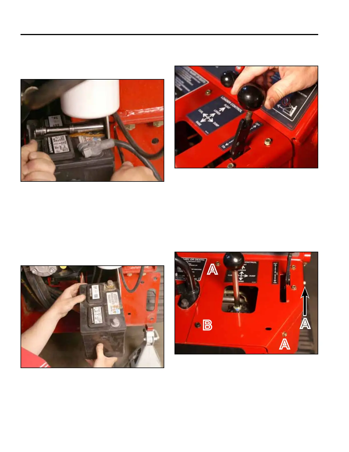
12. Slide the battery partially out of the battery mount.
Disconnect the negative battery cable from the
battery. Slide the battery out to access the positive
battery cable terminal. Disconnect the positive
battery cable. Remove the battery and battery guard
from the battery mount (Fig. 1709).
Fig 1709 PICT-4312a
13. Remove the knob from the brake handle (Fig. 1710).11. Using a 1/2” socket and wrench, remove the bolt,
washer and nut securing the battery clamp to the
frame. Remove the battery clamp (Fig. 1708).
Fig 1710 PICT-4342
Fig 1708 PICT-4310a
14. Using a 3/8” socket, remove the 3 self tapping
screws that secure the right panel to the control
panel assembly. Using a 3/8” socket and a 7/16”
socket, remove the bolt and nut securing the lower
left corner of the right panel to the control panel
assembly (Fig. 1711).
Fig 1711 PICT-4341
A. Self-tapping screw (3) B. Bolt and nut
A
B
A
A