BRAKES
8-28 Rev. 000 TX525 Service Manual
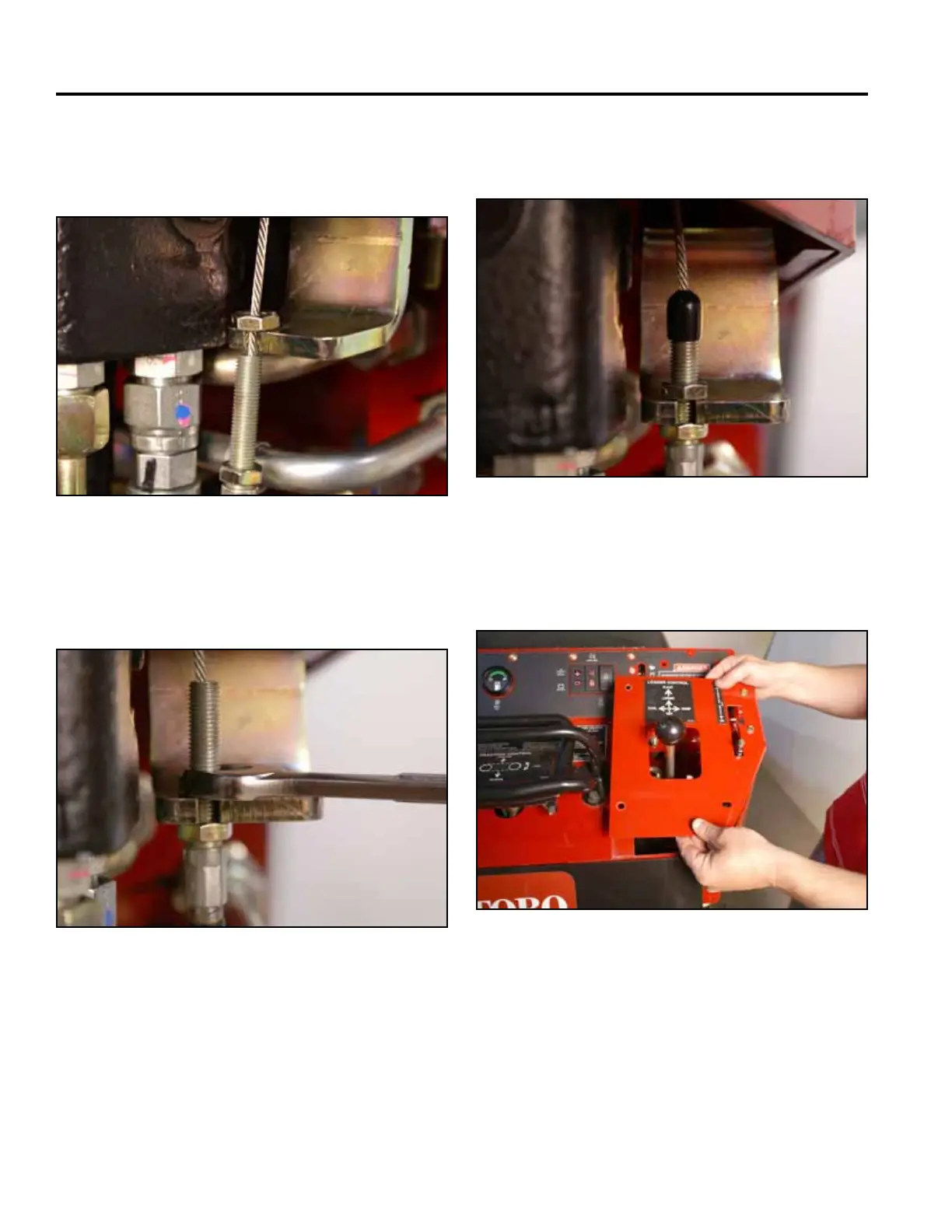
7. Pull down on the cable and slide the threaded
portion of the brake cable assembly into the slot
(Fig. 1737).
9. Slide the rubber boot down over the end of the
threaded portion of the brake cable (Fig. 1739).
Fig 1737 PICT-4414
Fig 1739 PICT-4420
10. Position the right panel onto the control panel as-
sembly (Fig. 1740).
8. Thread the upper nut onto the threaded portion of
the brake cable and tighten (Fig. 1738).
Fig 1740 PICT-4343a
Fig 1738 PICT-4419a