BRAKES
8-29TX525 Service Manual Rev. 000
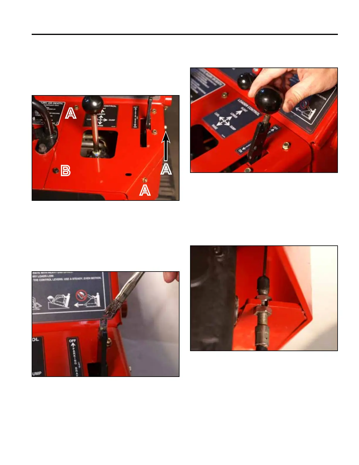
11. Using a 3/8” socket, install 3 self-tapping screws that
secure the right panel to the control panel assembly.
Using a 3/8” socket and a 7/16” socket, install the
bolt and nut securing the lower left corner of the right
panel to the control panel assembly (Fig. 1741).
13. Install the knob onto the brake handle (Fig. 1743).
Fig 1741 PICT-4341
Fig 1743 PICT-4342
12. Apply thread locking compound (Loctite 416 or
equivalent) to brake handle threads (Fig. 1742).
Note: If the brake plates extend out past the frame,
the brake cable adjustment nuts should be
adjusted upward on the brake cable adjust-
ment threads (Fig. 1744).
A. Self-tapping screw (3) B. Bolt and nut
Fig 1742 PICT-5526
Fig 1744 PICT-4340
A
B
A
A