8-20 Phaser 6250 Color Laser Printer Service Manual
Printer Chassis/Feeder Assembly
1. Remove the Imaging Unit and protect it from exposure to light.
2. Remove the Link Actuator (page 8-32).
3. Remove the Top Main Cover (page 8-9).
4. Remove the Right and Left Side Covers (page 8-11).
5. On the left side of the printer, disconnect P/J2361 (gray) from the Printer Chassis.
6. On the right side of the printer, disconnect P/J210 (yellow) from the Printer
Chassis.
7. Disconnect P/J47 (yellow/blue) from the Motor Driver Circuit Board on the right
side of the printer.
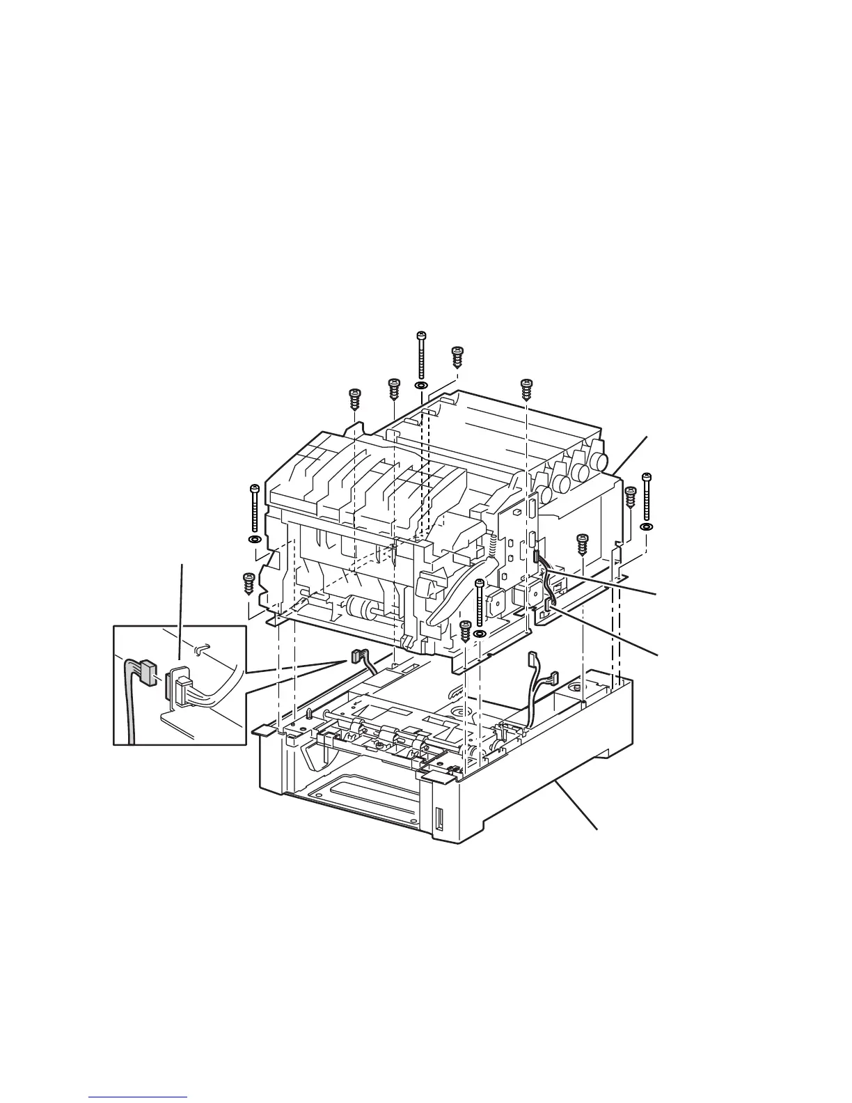
8. Remove the 8 short screws securing the Printer Chassis (item #1) to the Feeder
Assembly (item #2).
Caution
It is easy to strip the long screws, use caution when removing and replacing.
6250-141
2
1
P/J47
P/J210
P/J2361

 Loading...


