www.dadehpardazan.ir 88594014-15
5.4 Position Control
5-45
(2) Electronic Gear Ratio Setting Examples
The following examples show electronic gear ratio settings for different load configurations.
Example: The number on divisions on the serial converter unit: 256
Refer to the following equation to determine the electric gear
ratio.
Step Operation Load Configuration
1 Check the scale pitch. 0.02 mm (20 m)
2 Determine the reference
unit.
1 reference unit: 0.001 mm (1 m)
3 Calculate the electronic
gear ratio.
4 Set parameters. Pn20E 256
Pn210 20
A 20(µm)
B
1(µm)
=
× 256
A
B
+
−
×256
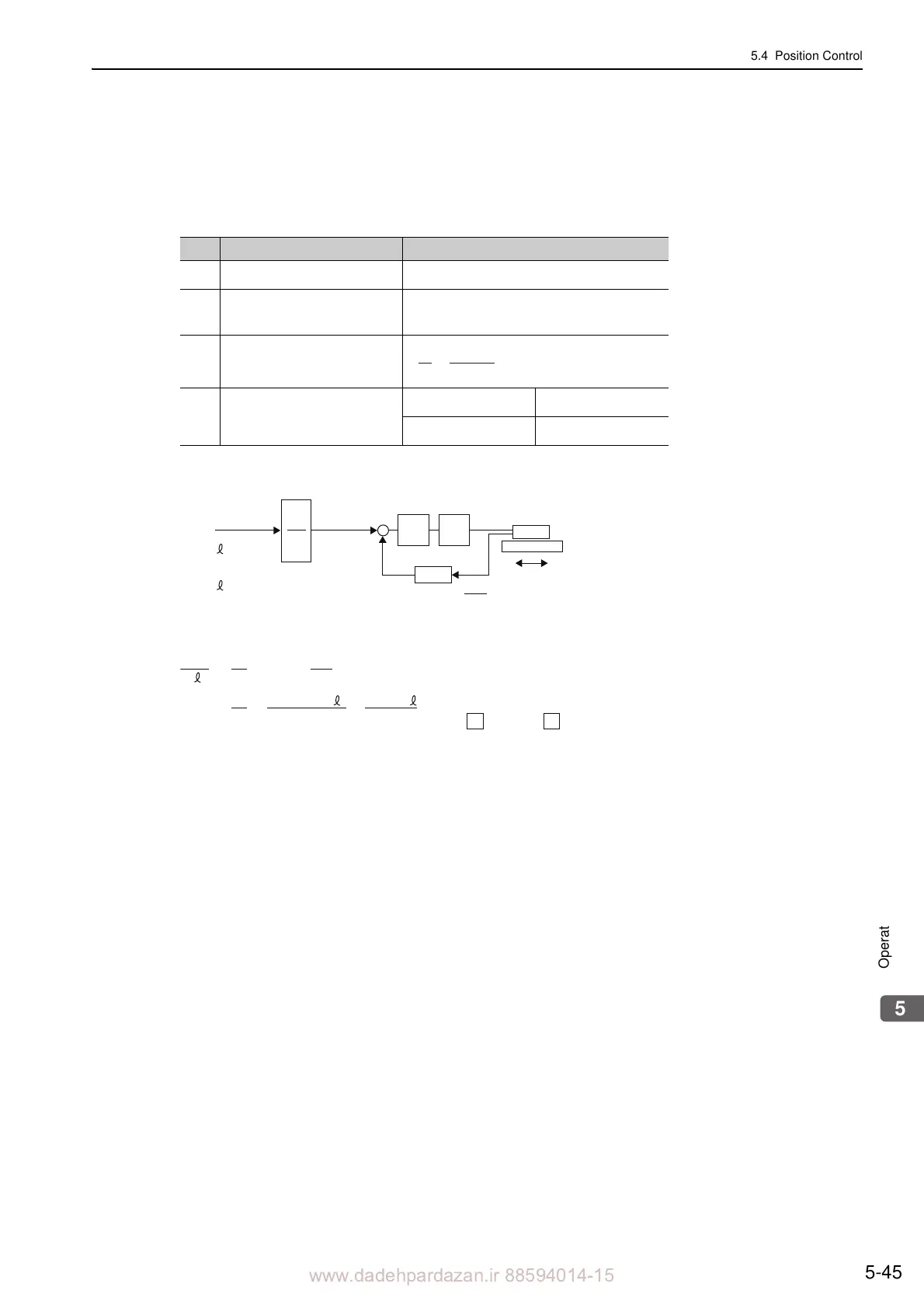
Movement distanceL㧔mm㧕
Ps
L
L㧔mm㧕㧦Movement distance
Posi-
tion
loop
Speed
loop
Reference pulse
㧔mm/P㧕
Δ
Δ
㧔mm/P㧕㧦Reference unit
Ps㧔mm㧕㧦Scale pitch
mm/scale pitch㧕
Servomotor
L
Ps
× L
B
Δ
A
Ps
L
Ps
Δ
Δ
×
()
= 256 ×
B
A
()
==
256
× L × 256 ×
Set A and B with the following parameters.
A
㧦Pn20E
B
㧦Pn210