www.dadehpardazan.ir 88594014-15
6.2 Tuning-less Function
6-15
Note: If the rigidity level is changed, the automatically set notch filter will be canceled. If vibration occurs, however, the
notch filter will be set again automatically.
(3) Operating Procedure with Panel Operator
(4) Alarm and Corrective Actions
The autotuning alarm (A.521) will occur if resonance sound is generated or excessive vibration occurs during
position control. In such case, take the following actions.
Resonance Sound
Reduce the setting of the rigidity level or load level.
Excessive Vibration during Position Control
Take one of the following actions to correct the problem.
• Increase the setting of the rigidity level or reduce the load level.
• Increase the setting of Pn170.3 or
reduce the setting of Pn170.2.
6
Press the Key to complete the tuning-less func-
tion. The screen in step 1 will appear again.
(cont’d)
Step Display after Operation Keys Operation
㧾㨁㧺㧲㨁㧺㧯㨀㧵㧻㧺
㧲㨚㧜㧟㧜
㧲㨚㧞㧜㧜
㧲㨚㧞㧜㧝
㧲㨚㧞㧜㧞
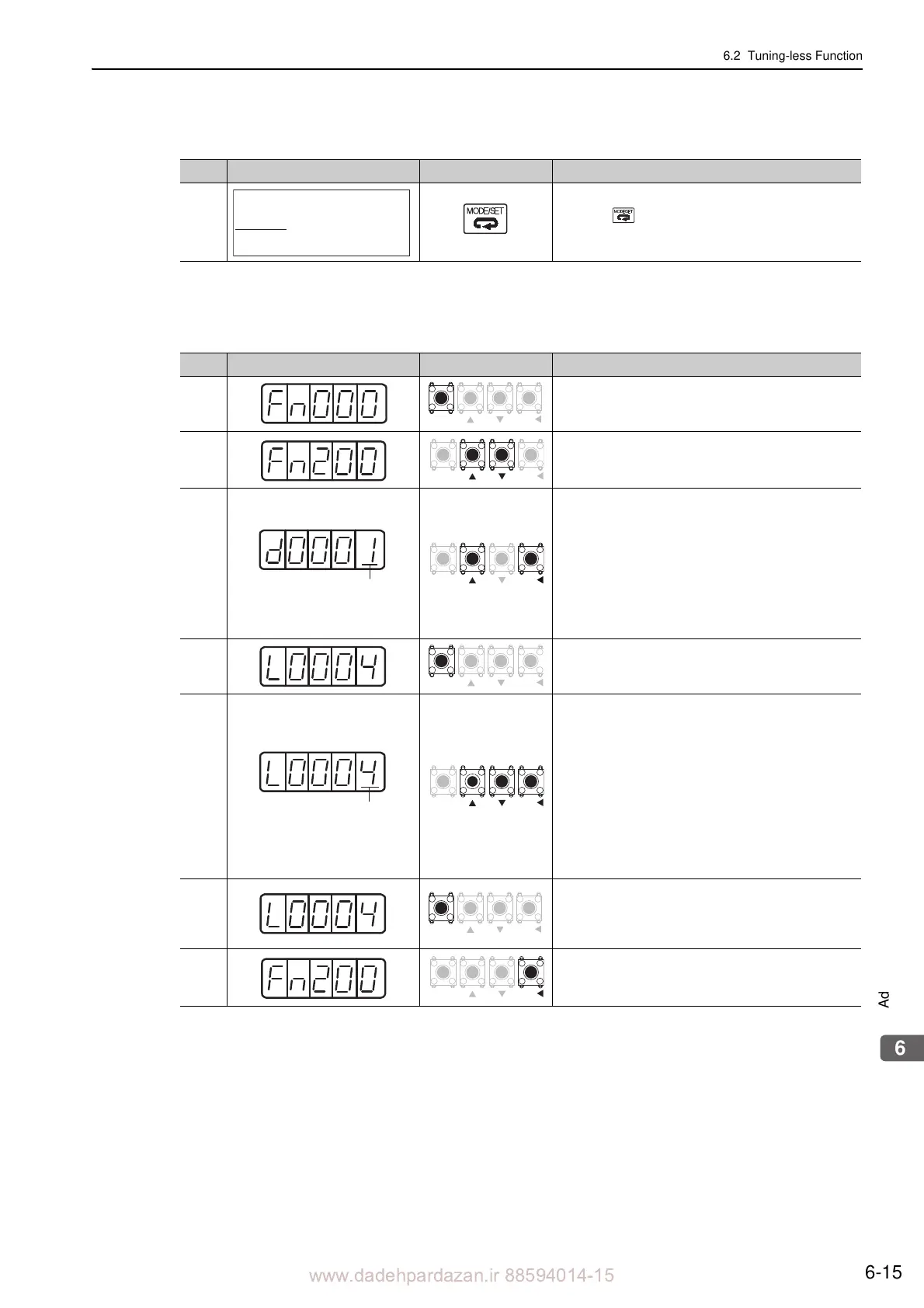
Step Display after Operation Keys Operation
1
Press the MODE/SET Key to select the utility func-
tion.
2 Press the UP or the DOWN Key to select
the Fn200.
3
Press the DATA/SHIFT Key for approximately one
second to display the
load level of the tuning-less
mode setting screen.
Note:
If the response waveform causes oversho
oting or if
the mass of the load is 30 times greater or more than
that of the servomotor in the mass ratio (i.e., outside
the scope of product guarantee), press the UP Key
and change the load level to 2.
4
Press the MODE/SET Key to display
the rigidity
level of the tuning-less mode setting screen.
5
Press the UP or the DOWN Key to select the rigidity
le
vel.
Select the rigidity level from 0 to 4. The larger the
value,
the higher the gain is and the better response
performance will be. (The factory setting is 4.)
Notes:
• Vibration may occur if the rigidity level
is too high.
Lower the rigidity level if vibration occurs.
• If high-frequency noise is generated, press
the
DATA/SHIFT Key to automatically set a notch fil-
ter to the vibration frequency.
6
Press the MODE/SET Key. “d
onE” will flash for
approximately one second and then L0004 will be
displayed. The settings are saved in the SERVO-
PACK.
7
Press the DATA/SHIFT Key for approximately one
second. "Fn200"
is displayed again.
Load level
MODE
SET
DATA
MODE
SET
DATA
 Loading...


