www.dadehpardazan.ir 88594014-15
9 Troubleshooting
9.1.2 Troubleshooting of Alarms
9-10
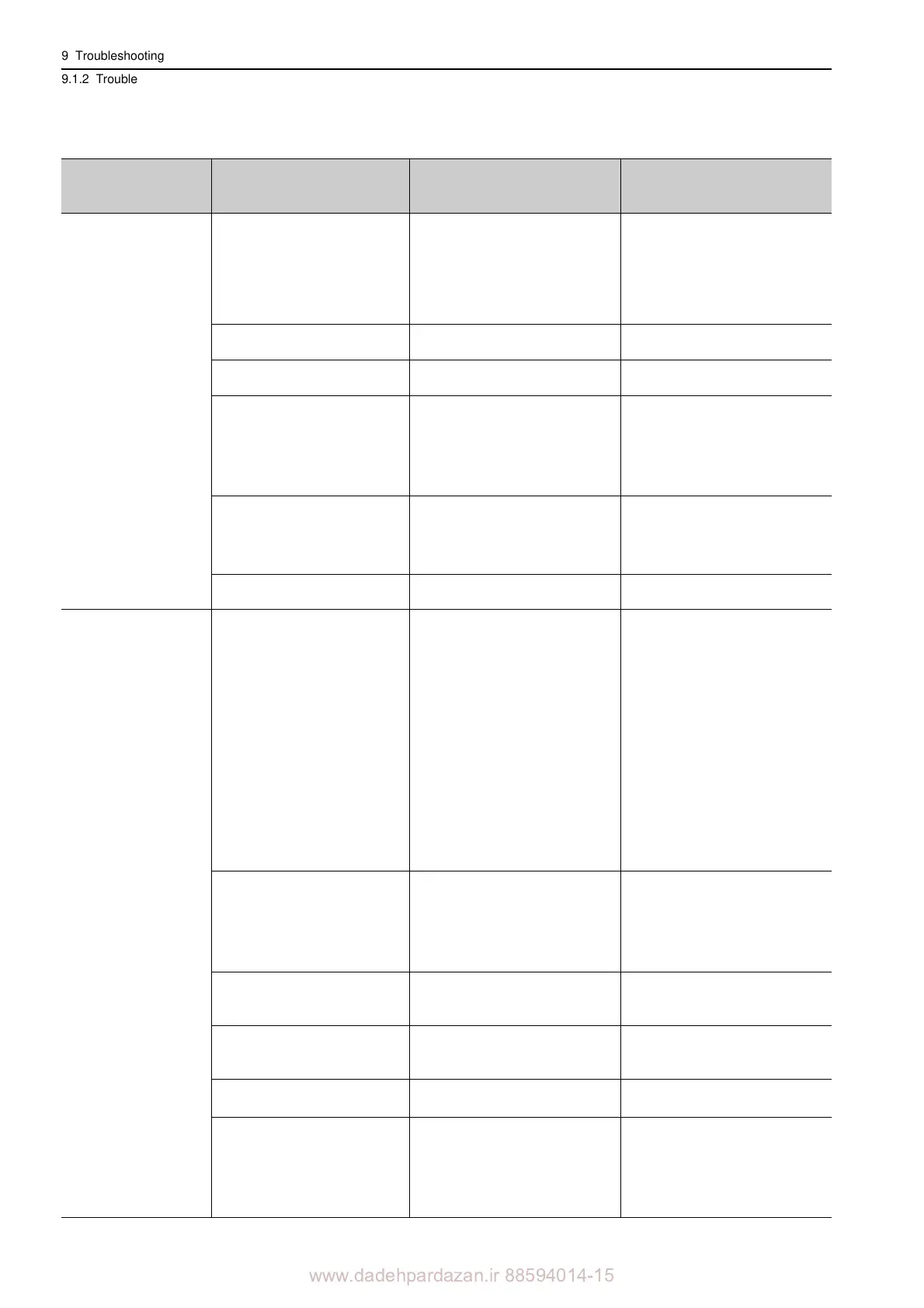
A.330:
Main Circuit Power
Supply Wiring Err
or
(Detected when the
power t
o the main circuit
is turned ON.)
The regenerative resistor discon-
nected when the SERVOPACK
power supply voltage was high.
Measure the resistance of the regen-
erative resistor using a measuring
instrument.
When using a regenerative resistor
built in the
SERVOPACK:
Replace the SERVOPACK.
When using an external regenera-
tive resistor:
Replace the external regenerative
re
sistor.
In the AC power input mode, DC
p
ower was supplied.
Check the power supply to see if it
is a DC power supply.
Correct the settings to match the
actual power supply specifications.
In the DC power input mode, AC
p
ower was supplied.
Check the power supply to see if it
is an AC power supply.
Correct the settings to match the
actual power supply specifications.
Regenerative resistor capacity
(
Pn600) is set to a value other
than 0 for a SGDV-R70, -R90, -
1R6, -2R1, or -2R8 SERVO-
PACK, and an external regenera-
tive resistor is not connected.
Check the external regenerative
resistor
connection and the value of
the Pn600.
Connect the external regenerative
resistor, or set Pn600 to 0 if no
regenerative resistor is required.
The jumper between the power
supply terminals B
2 and B3 is
removed for the SERVOPACKs
other than the SERVOPACKs
shown above.
Confirm that a jumper is mounted
between the power supply terminals
B2 and B3.
Correctly mount a jumper.
A SERVOPACK fault occurred.
The SERVOPACK may be faulty.
Replace the
SERVOPACK.
A.400:
Overvoltage
(Detected in the SER-
VOPACK main circuit
power supply sectio
n.)
• For 100-VAC SERVOPACKs:
The AC power supply voltage
exceeded 145 V
.
• For 200-VAC SERVOPACKs:
The AC power supply voltage
exceeded 290 V
.
• For 400-VAC SERVOPACKs:
The AC power supply voltage
exceeded 580 V
.
• For 200-VAC SERVOPACKs:
with DC
power supply input:
The DC power supply voltage
exceeded 410 V.
• For 400-VAC SERVOPACKs:
The
DC power supply voltage
exceeded 820 V.
Measure the power supply voltage.
Set AC/DC power supply voltage
wi
thin the specified range.
The power supply is unstable, or
was
influenced by a lightning
surge.
Measure the power supply voltage.
Improve the power supply condi-
tions by installing a surge absorber,
etc.
Then, turn the power supply
OFF and ON again. If the alarm still
occurs, the SERVOPACK may be
faulty. Replace the SERVOPACK.
Voltage for AC power supply was
too high durin
g acceleration or
deceleration.
Check the power supply voltage and
the speed and force during opera-
tion.
Set AC power supply voltage within
the
specified range.
The external regenerative resis-
tance is too high for the actual
operating conditions.
Check the operating conditions and
the reg
enerative resistance.
Select a regenerative resistanc
e
value appropriate for the operating
conditions and load.
The mass ratio exceeded the
allowable value.
Confirm that the mass ratio is
within the allowable range.
Increase the deceleration time, or
reduce the load.
A SERVOPACK fault occurred.
Turn the control power OFF and
t
hen ON again while the main cir-
cuit power supply is OFF. If the
ala
rm still occurs, the SERVO-
PACK may be faulty. Replace the
S
ERVOPACK.
(cont’d)
Alarm Number:
Alarm Name
(Alarm Description)
Cause Investigative Actions Corrective Actions