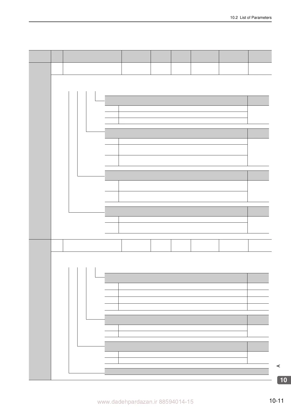
No.
Servomotor power OFF or Alarm Gr.1 Stop Mode
Reference
Section
0 Stops the servomotor by applying DB (dynamic brake).
5.2.6
1 Stops the servomotor by applying DB and then releases DB.
2 Makes the servomotor coast to a stop state without using the DB.
Overtravel (OT) Stop Mode
Reference
Section
0 Stops in accordance with the setting of Pn001.0.
5.2.4
1 Sets the force of Pn406 to the maximum value, decelerates the servomotor to a stop,
and then sets it to servolock state.
2 Sets the force of Pn406 to the maximum value, decelerates the servomotor to a stop,
and then sets it to coasting state.
AC/DC Power Input Selection
Reference
Section
0 Applicable to AC power input: Input AC power supply through L1, L2, and L3
terminals.
3.1.4
1 Applicable to DC power input: Input DC power supply between B1/ + and 2, or input
DC power supply between B1/ + and .
Warning Code Output Selection
Reference
Section
0 ALO1, ALO2, and ALO3 output only alarm codes.
5.10.2
1 ALO1, ALO2, and ALO3 output both alarm codes and warning codes. While warning
codes are output, ALM signal output remains ON (normal state).
4th 3rd 2nd 1st
digit digit digit digit
n.
Speed/Position Control Option (T-REF Terminal Allocation)
Reference
Section
0
T-REF not allocated
–
1
Uses T-REF as an external force limit input.
5.8.3
2
Uses T-REF as a force feedforward input.
6.9.2
3
Uses T-REF as an external force limit input when /P-CL and /N-CL are ON.
5.8.4
Force Control Option (V-REF Terminal Allocation)
Reference
Section
0 V-REF not allocated
5.5.4
1 Uses V-REF as an external speed limit input.
Absolute Linear Scale Usage
Reference
Section
0 Uses absolute linear scale as an absolute linear scale.
5.9
1 Uses absolute linear scale as an incremental linear scale.
Reserved (Do not change.)
4th 3rd 2nd 1st
digit digit digit digit
n.

 Loading...


