4.2 Using the Digital LED Operator
110 YASKAWA TM.V1000.01 V1000 Drive Installation & Start-Up Manual (Preliminary 01-19-07)
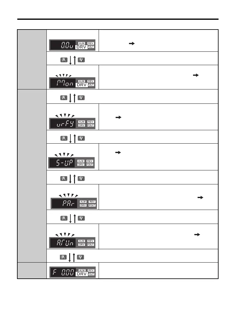
Drive Mode
Output Voltage Reference
Scroll through o1-01 (User Monitor Selection) until the desired
contents appear.
Monitor Display
The initial display for the U1 status monitors appears. Refer to
Drive Status Monitors: U1-01 to U6-19 on page 150.
Programming
Mode
Verify Function
Lists all parameters that have been edited or changed from default
settings. Refer to Verifying Parameter Changes: Verify Menu
on page 114.
Setup Mode
A select list of parameters necessary to get the drive operational
quickly. Refer to The Setup Group within the Programming
Mode on page 112. Note: A1-06 (Application Presets) can be used
to instantly set a series of parameters to optimum values for specific
applications.
Parameter Setting
Allows the user to access and edit all parameter settings.
Auto-Tuning
Motor parameters are calculated and set automatically. Refer to
Auto-Tuning on page 161.
Drive Mode Returns to the frequency reference display screen.

 Loading...


