4.4 Basic Parameter Adjustments
YASKAWA TM.V1000.01 V1000 Drive Installation & Start-Up Manual (Preliminary 01-19-07) 131
Start-Up Programming &
Operation
4
Using a Single Analog Signal (V or I) as the Frequency Reference
Control Circuit Terminal A1 (Voltage Input):
When entering the main frequency reference with a voltage signal, use the voltage
input set up in control circuit terminal A1.
Figure 4.12
Figure 4.12 Voltage Input for the Main Frequency Reference
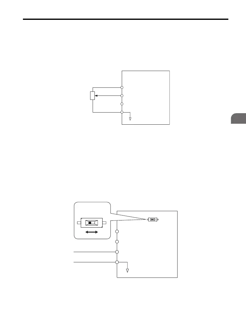
Control Circuit Terminal A2 (Voltage/Current Input):
Use the following settings if the frequency reference value is input by a current
signal at analog input A2:
• Set the signal level for analog input A2 to current input (H3-09 = 2 for 4-20 mA,
H3-09 = 3 for 0-20 mA).
• Set the function for analog input A2 to frequency reference (H3-10 = “0”) to
command terminal A2 to be a frequency reference.
• Set DIP switch S1 to the I position for a current signal input.
Figure 4.13
Figure 4.13 Current Input for the Main Speed Reference
Drive
A1
A2
Main Frequency Reference
(voltage input)
0 to 10 V
Main Frequency Reference
(voltage input)
AC
Frequency Reference
Common
2 kohm
㧗V (+10.5 V㧘20 mA)
Drive
A1
A2
Main Frequency Reference
(voltage input)
Main Frequency Reference
(current input)
AC
Frequency Reference
Common
㧗V (+10.5 V, 20 mA)
(0) 4 - 20 mA input
DIP switch S1
VI

 Loading...


