4.4 Basic Parameter Adjustments
132 YASKAWA TM.V1000.01 V1000 Drive Installation & Start-Up Manual (Preliminary 01-19-07)
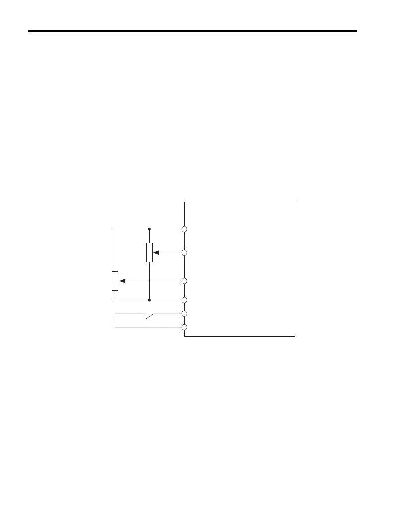
Switching between Main/Auxiliary Frequency References
To configure the frequency reference to switch between analog input A1 and A2
(main/aux frequency switch), use the following set up:
1. Set the frequency reference source to terminals (b1-01 = “1”).
2. Set one of the digital inputs to auxiliary reference 1 (H1-®® = “3” (preset for
terminal S5).
3. Set input signal type of terminal A2 using dip switch S1 and parameter H3-09.
4. Set the function of analog input A2 to Auxiliary frequency (H3-10 = “3”).
When the digital input assigned in step 2 is off, terminal A1 is the frequency
reference input. If it is closed, the A2 input value becomes the frequency reference.
The active acceleration / deceleration times are used for the change-over between
the values
Figure 4. 14
Figure 4.14 Switching between Main/Auxiliary Frequency References
Drive
A1
A2
Main Frequency Reference
(voltage input)
Aux Frequency Reference 1
AC
S5
Frequency Reference Common
Multi-Function Digital Input
SC
Digital Input Common
2 kohm
㧗V (+10.5 V, 20 mA)
2 kohm
(voltage input)

 Loading...


