4.4 Basic Parameter Adjustments
YASKAWA TM.V1000.01 V1000 Drive Installation & Start-Up Manual (Preliminary 01-19-07) 137
Start-Up Programming &
Operation
4
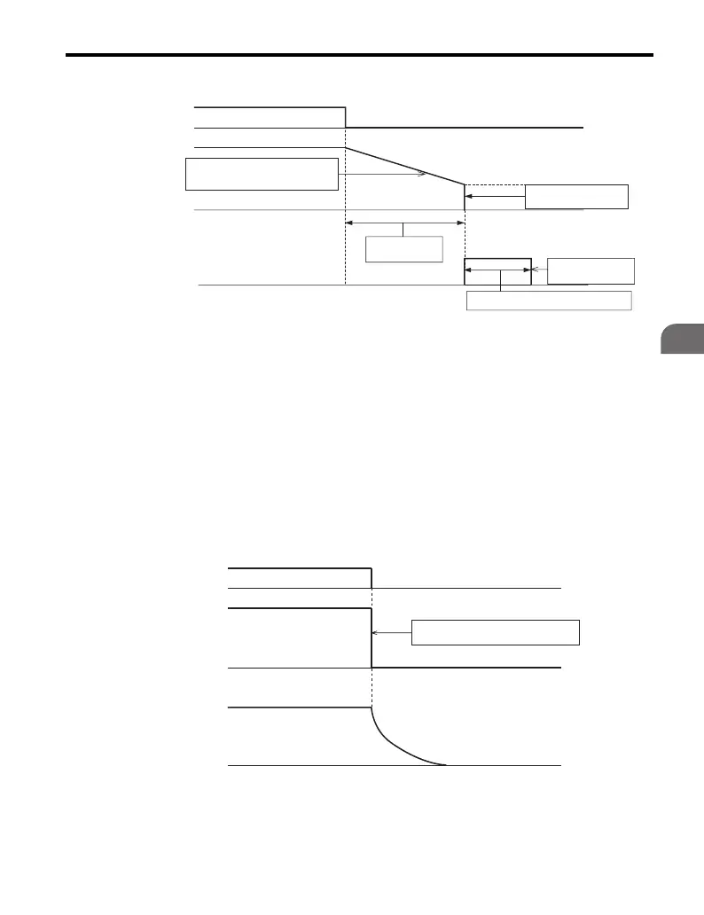
Figure 4.17
Figure 4.17 Ramp to Stop
Note: When using PM Open Loop Vector Control (A1-02 = 5), the time set to b2-13 (Short
Circuit Braking Time at Stop) is used instead of the DC Injection braking time set to
b2-04. Short Circuit Braking is a function that connects all three phases of the motor
to either the positive or negative DC bus to provide motor braking torque.
■
Coast to Stop (b1-03 = 1)
When the stopping method is set for coast to stop (b1-03 = 1), the drive output
voltage will be interrupted when the stop command is entered (i.e., the run
command is turned off). The motor will coast to a stop at the rate determined by the
load inertia.
Figure 4.18
Figure 4.18 Coast to Stop
Run Command
Decelerates according to the
specified deceleration time
Zero Speed Level
(b2-01)
DC Injection
Current (b2-02)
DC Braking Time at Stop (b2-04)
Decel Time
(C1-02, etc.)
Output Frequency
DC Injection Braking
ON OFF
Drive output voltage interrupted
Run Command
Output Voltage
Motor Rotations
ON OFF

 Loading...


