5.6 Alarm Detection
YASKAWA TM.V1000.01 V1000 Drive Installation & Start-Up Manual (Preliminary 01-19-07) 225
Troubleshooting
5
Cause Possible Solutions
Minor Fault
Output
(H2- = 10)
A data error occurred due to noise.
• Check the various options available to minimize the
effects of noise.
• Take steps to counteract noise in the control circuit
wiring, main circuit lines and ground wiring.
• Try to reduce noise on the controller side.
• If the disturbance is caused by switching magnetic
contactors or other equipment, use surge absorbers on
these devices.
• Use cables recommended by Yaskawa, or another type of
shielded line. The shield should be grounded on the
controller side or on the drive input power side.
• All wiring for communications devices should be
separated from drive input power lines. Install a noise
filter to the input side of the drive input power.
YES
Option card is damaged.
If there are no problems with the wiring and the fault
continues to occur, replace the option card.
YES
The option card is not properly
connected to the drive.
• The connector pins on the option card are not properly
lined up with the connector pins on the drive.
• Reinstall the option card.
YES
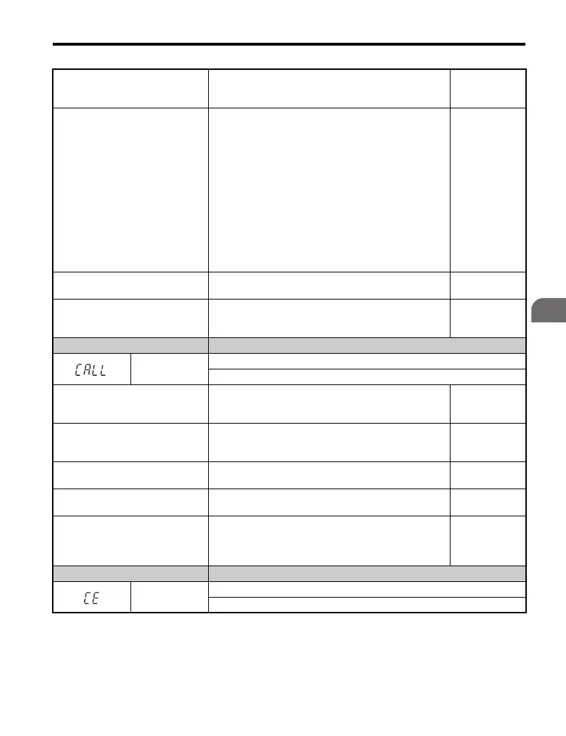
LED Operator Display Minor Fault Name
CALL
Serial Communication Transmission Error
Communication has not yet been established.
Cause Possible Solutions
Minor Fault
Output
(H2- = 10)
Communications wiring is faulty,
there is a short circuit, or something
is not connected properly.
• Check for wiring errors.
• Correct the wiring.
• Remove and ground shorts and reconnect loose wires.
YES
Programming error on the master
side.
Check communications at start-up and correct
programming errors.
YES
Communications circuitry is
damaged.
• Perform a self-diagnostics check.
• Replace the drive if the fault continues to occurs.
YES
Terminal resistance setting is
incorrect.
The terminal slave drive must have the internal terminal
resistance switch set correctly. Place DIP switch S2 to the
ON position. Refer to MEMOBUS/Modbus Switch
Settings on page 90.
YES
LED Operator Display Minor Fault Name
CE
MEMOBUS/Modbus Communication Error
Control data was not received correctly for two seconds.

 Loading...


