5.6 Alarm Detection
YASKAWA TM.V1000.01 V1000 Drive Installation & Start-Up Manual (Preliminary 01-19-07) 233
Troubleshooting
5
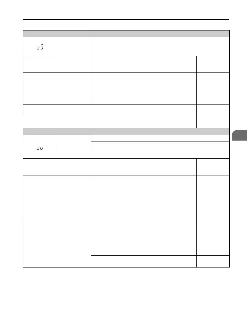
LED Operator Display Minor Fault Name
oS
Overspeed (for Simple V/f with PG)
Pulse input (RP) indicates that the motor speed feedback exceeded the setting
in F1-08.
Cause Possible Solutions
Minor Fault
Output
(H2- = 10)
Overshoot or undershoot is
occurring.
• Adjust the gain by using the pulse train input parameters
(H6-02 through H6-05).
Adjust the speed feedback accuracy.
• Increase the settings for C5-01 (Speed Control
Proportional Gain 1) and reduce C5-02 (Speed Control
Integral Time 1).
YES
PG pulse settings are incorrect.
Set the H6-02 (Pulse Train Input Scaling) = 100%, the
number of pulses during maximum motor revolutions.
YES
Parameter settings are inappropriate.
Check the setting for the overspeed detection level and the
overspeed detection time (F1-08 and F1-09).
YES
LED Operator Display Minor Fault Name
ov
DC Bus Overvoltage
The DC bus voltage exceeded the trip point.
For 200 V class: approximately 410 V
For 400 V class: approximately 820 V (740 V when E1-01 < 400)
Cause Possible Solutions
Minor Fault
Output
(H2- = 10)
Surge voltage is present in the drive
input power.
• Install a DC reactor or an AC reactor.
• Voltage surge can result from a thyristor convertor and a
phase advancing capacitor operating on the same drive
input power system.
YES
• The motor has short-circuited.
• Ground current has over-charged
the main circuit capacitors via the
drive input power.
• Check the motor power cable, relay terminals and motor
terminal box for short circuits.
• Correct grounding shorts and turn the power back on.
YES
Noise interference causes the drive to
operate incorrectly.
• Review the possible solutions provided for handling noise
interference.
• Review the section on handling noise interference and
check the control circuit lines, main circuit lines and
ground wiring.
• If the magnetic contactor is identified as a source of noise,
install a surge protector to the MC coil.
YES
Set the number of fault restarts (L5-01) to a value other
than 0.
YES

 Loading...


