6.3 Periodic Maintenance
YASKAWA TM.V1000.01 V1000 Drive Installation & Start-Up Manual (Preliminary 01-19-07) 277
Periodic Inspection &
Maintenance
6
Refer to Recommended Periodic Inspection on page 273 for more details.
Table 6.4 Performance Life Monitors for Replacing Components
■
Maintenance Alarm Signals
The drive has a maintenance monitor. Table 6.5 describes maintenance alarm
programming.
Digital LED Operator Alarm Display
The LED digital operator can display an alarm to warn of approaching maintenance
periods.
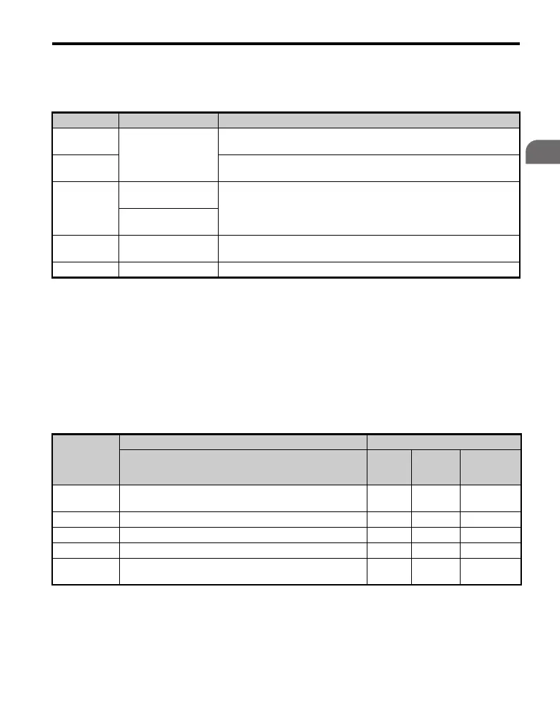
Table 6.5 Maintenance Alarm Programming
NOTICE: After replacing parts, reset the appropriate maintenance parameters (o4-03, o4-05,
o4-07, and o4-09) to 0. If these parameters are not reset, the function will continue to count
down the performance life of the new replaced components.
Parameter Component Contents
U4-03
Cooling Fan
Displays the accumulated operation time of the cooling fan, from 0 to
65535 hours. This value is automatically reset to 0 once it reaches 65535.
U4-04
Displays the accumulated cooling fan operation time as a percentage of the
specified maintenance period (displayed in percent%).
U4-05
Main Circuit (DC bus)
Electrolytic Capacitors
Displays the accumulated time the capacitors are used as a percentage of
the specified maintenance period.
Control Circuit
Electrolytic Capacitors
U4-06
Inrush (pre-charge)
relay
Displays the number of times the drive is powered up as a percentage of
the maintenance period.
U4-07 IGBT Displays the percentage of the maintenance period reached by the IGBTs.
Parameter
Parameter Name Control Mode
Operator Display V/f
Open
Loop
Vector
Open Loop
Vector for
PM
o4-03
Cooling Fan Maintenance Setting
(Operation Time)
AA A
o4-05 Capacitor Maintenance Setting A A A
o4-07 Inrush Prevention Relay (pre-charge) Maintenance Setting A A A
o4-09 IGBT Maintenance Setting A A A
o4-10
IGBT Maintenance Timer Setting
(Forecast Function)
AA A

 Loading...


