EasyManuals Logo

YASKAWA V1000 Series Installation & Start-Up Manual

YASKAWA V1000 Series
470 pages
To Next Page IconTo Next Page
To Previous Page IconTo Previous Page
Page #30 background imageLoading...
Page #30 background image
1.4 Component Names
30 YASKAWA TM.V1000.01 V1000 Drive Installation & Start-Up Manual (Preliminary 01-19-07)
Figure 1. 5
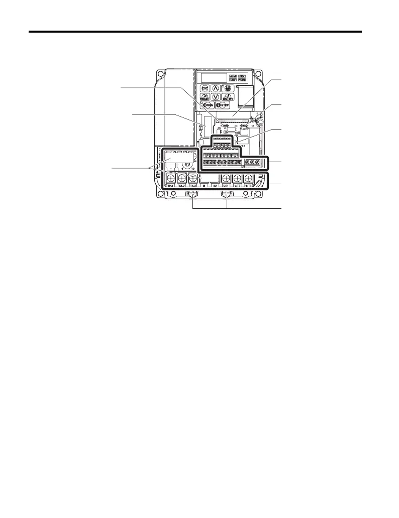
Figure 1.5 Front View of IP20/Open-Chassis Type Components
Three-phase 200 Vac Model CIMR-V2A0012A
A Terminal board connector F Ground terminal
B DIP switch S1
Refer to Terminal A2 Switch on
page 88
G Terminal cover
C DIP switch S3
Refer to Sinking/Sourcing
Mode Switch on page 84
H (unused)
D Control circuit terminal
Refer to Control Circuit Wiring
on page 75
I Option card connector
Refer to Connecting an Option
Card on page 309
E Main circuit terminal
Refer to Wiring the Main
Circuit Terminal on page 73
J DIP switch S2
Refer to MEMOBUS/Modbus
Termination on page 90
J
A
B
C
D
E
F
G
I

Table of Contents

Other manuals for YASKAWA V1000 Series

Questions and Answers:

Question and Answer IconNeed help?

Do you have a question about the YASKAWA V1000 Series and is the answer not in the manual?

YASKAWA V1000 Series Specifications

General IconGeneral
ModelV1000 Series
SeriesV1000
Output Frequency0.1 to 400 Hz
Overload Capacity150% for 60 seconds
TypeAC Drive
Control MethodV/f Control
Input Voltage200-240V, 380-480V
Output Voltage0 to Input Voltage
Power Range0.1 to 18.5 kW
Horsepower0.2 to 25 HP
Protection FeaturesOvercurrent, Overvoltage, Undervoltage, Overheating, Short Circuit, Ground Fault
Communication InterfacesModbus RTU
EnclosureIP20
Ambient Temperature-10 to +50°C
Storage Temperature-20 to +60°C
Humidity5 to 95% RH (non-condensing)
Cooling MethodFan Cooled

Related product manuals