EasyManuals Logo

YASKAWA V1000 Series Installation & Start-Up Manual

YASKAWA V1000 Series
470 pages
To Next Page IconTo Next Page
To Previous Page IconTo Previous Page
Page #303 background imageLoading...
Page #303 background image
7.4 Installing Peripheral Devices
YASKAWA TM.V1000.01 V1000 Drive Installation & Start-Up Manual (Preliminary 01-19-07) 303
Peripheral Devices &
Options
7
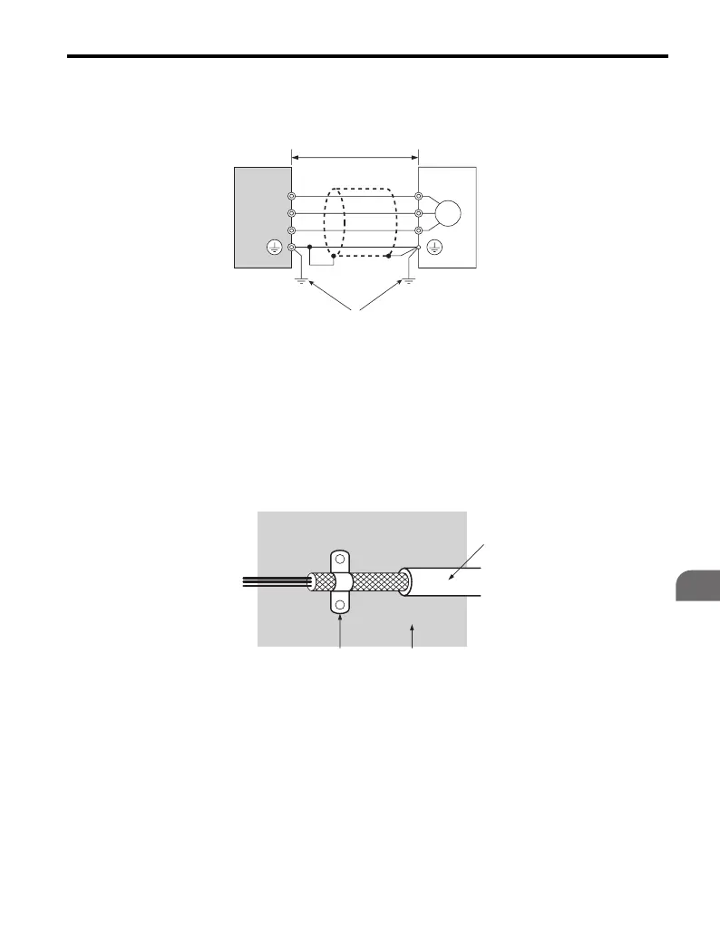
4. Keep wiring as short as possible. Ground the shield on both the drive side
and the motor side (Figure 7.9).
Figure 7.9
Figure 7.9 Installation Method
5. Ground the largest possible surface area of the shield to the metal conduit
when using braided shield cable. Yaskawa recommends using a cable
clamp (Figure 7.10).
Figure 7.10
Figure 7.10 Ground Area
A Drive D Metal conduit
B 20 m max cable length
between drive and motor
E Ground wire should be as
short as possible.
C–Motor
A Braided shield cable C Cable clamp (conductive)
B–Metal panel
A
B
D
E
C
M
U/T1
V/T2
W/T3
U
V
W
C
B
A

Table of Contents

Other manuals for YASKAWA V1000 Series

Questions and Answers:

Question and Answer IconNeed help?

Do you have a question about the YASKAWA V1000 Series and is the answer not in the manual?

YASKAWA V1000 Series Specifications

General IconGeneral
ModelV1000 Series
SeriesV1000
Output Frequency0.1 to 400 Hz
Overload Capacity150% for 60 seconds
TypeAC Drive
Control MethodV/f Control
Input Voltage200-240V, 380-480V
Output Voltage0 to Input Voltage
Power Range0.1 to 18.5 kW
Horsepower0.2 to 25 HP
Protection FeaturesOvercurrent, Overvoltage, Undervoltage, Overheating, Short Circuit, Ground Fault
Communication InterfacesModbus RTU
EnclosureIP20
Ambient Temperature-10 to +50°C
Storage Temperature-20 to +60°C
Humidity5 to 95% RH (non-condensing)
Cooling MethodFan Cooled

Related product manuals