EasyManuals Logo

YASKAWA V1000 Series Installation & Start-Up Manual

YASKAWA V1000 Series
470 pages
To Next Page IconTo Next Page
To Previous Page IconTo Previous Page
Page #305 background imageLoading...
Page #305 background image
7.4 Installing Peripheral Devices
YASKAWA TM.V1000.01 V1000 Drive Installation & Start-Up Manual (Preliminary 01-19-07) 305
Peripheral Devices &
Options
7
Single-Phase 200 V Class
Figure 7.12
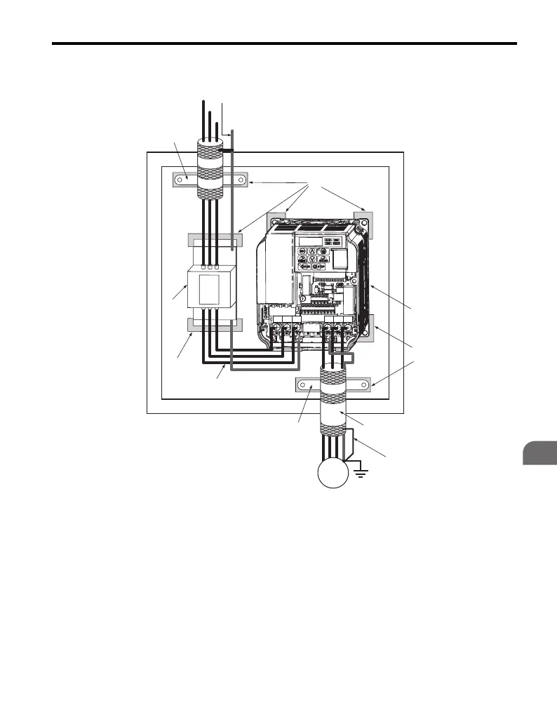
Figure 7.12 EMC Filter and Drive Installation for CE Compliance
(Single-Phase 200 V Class)
A Ground the cable shield F Motor cable (braided shield
cable, max. 20 m)
B Enclosure panel G Motor
C Metal plate H Cable clamp
D Grounding surface (remove
any paint or sealant)
I Max. distance between drive
and noise filter XX cm
E Drive J EMC noise filter
C
D
N
J
F
L
K
E
M
B
G
I
A
H
L3
L3
L2
L2
L1
L1
L3 L2 L1
E
L3
L2
L1
PE
R/L1 S/L2 T/L3
U/T1 V/T2
W/T3

Table of Contents

Other manuals for YASKAWA V1000 Series

Questions and Answers:

Question and Answer IconNeed help?

Do you have a question about the YASKAWA V1000 Series and is the answer not in the manual?

YASKAWA V1000 Series Specifications

General IconGeneral
ModelV1000 Series
SeriesV1000
Output Frequency0.1 to 400 Hz
Overload Capacity150% for 60 seconds
TypeAC Drive
Control MethodV/f Control
Input Voltage200-240V, 380-480V
Output Voltage0 to Input Voltage
Power Range0.1 to 18.5 kW
Horsepower0.2 to 25 HP
Protection FeaturesOvercurrent, Overvoltage, Undervoltage, Overheating, Short Circuit, Ground Fault
Communication InterfacesModbus RTU
EnclosureIP20
Ambient Temperature-10 to +50°C
Storage Temperature-20 to +60°C
Humidity5 to 95% RH (non-condensing)
Cooling MethodFan Cooled

Related product manuals