7.6 Connecting an Option Card
YASKAWA TM.V1000.01 V1000 Drive Installation & Start-Up Manual (Preliminary 01-19-07) 311
Peripheral Devices &
Options
7
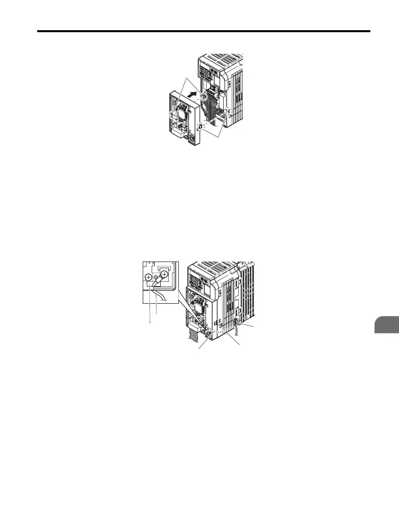
Figure 7.16
Figure 7.16 Attach Option Card
Note: Gently pack wires to fit behind the left and right side of the cover into the provided
recess.
5. Connect the lead from the drive ground terminal to the same terminal as
the option card lead.
The option card lead should exit through the holes provided on the
underside of the drive as it gets routed passed the ground terminal.
Figure 7.17
Figure 7.17 Lead Wire Connection
A – Line up the tab with the
mounting hole.
B – Line up the tab with the
mounting hole.
A – Drive ground terminal D – Ground lead through-hole
B – Route the lead wire on the
inside of the lower cover.
E – Ground lead
C – Ground lead
B
A
C
A
E
D
B

 Loading...


