A.3 Common Drive Specifications
YASKAWA TM.V1000.01 V1000 Drive Installation & Start-Up Manual (Preliminary 01-19-07) 321
Specifications
A
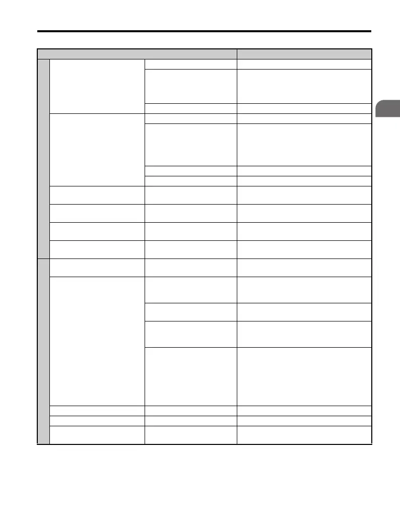
Inputs and Outputs
Outputs-Digital
Quantity 3
Signal Level Type
Qty. 2 Photo-Coupler Output:
DC 48 V 50 mA or less
Qty. 1 (fixed/fault): Form C, 250 Vac, 1 A or
less, 30 Vdc, 1 A or less
Programmable Functions Yes
Output-Digital Pulse Train
Quantity 1
Signal Level
Sourcing: Output volts and load impedance
+5 V at >1.5 kOhm, +8 V at >3.5 kOhm,
+10 V at >10 kOhm
Sinking: External power supply +15 Vdc +/-
10%, sinking current 16 mA or less
Frequency Range 0-33 kHz
Programmable Functions Yes
Frequency Setting
Power Supply
~ +10 V allowable max current 20 mA
Quick Disconnect Terminals Type
Yes, remove I/O via removable terminal
board
Removable Control Circuit
Terminal Board
~Yes
Control Power Supply ~
Separate input for 24 Vdc control power
supply (option)
Protective Features
DC Bus Charge Indicator ~
Dedicated charge lamp LED stays on until
bus is < 50 Vdc
Cooling Fin Overheat
Protection
~
Protects IGBTs by detecting heatsink
overheat due to a fan fault or temperature
increase. (“fan-lock” sensor)
Monitor
Yes, Detects heatsink temperature and issues
a pre-alarm
~
Yes,
Overheat Prevention
(frequency reduction method)
Cooling Method
Single phase 200 V class: cooling fan for
BA0010 - 0020
Three phase 200 V class: cooling fan for
2A0006 to 2A0020
Three phase 400 V class: cooling fan for
4A0005 to 4A0011
Smaller drives are self-cooled
Heat Sink Temperature Fault Method Pre-alarm, Coast, Ramp, Continue
Inertia Ride-Thru Function ~Yes (KEB)
Instantaneous Over Current
Trip Level
% Over 200% of drive rated current
Item Specification

 Loading...


