B.2 Parameter Table
342 YASKAWA TM.V1000.01 V1000 Drive Installation & Start-Up Manual (Preliminary 01-19-07)
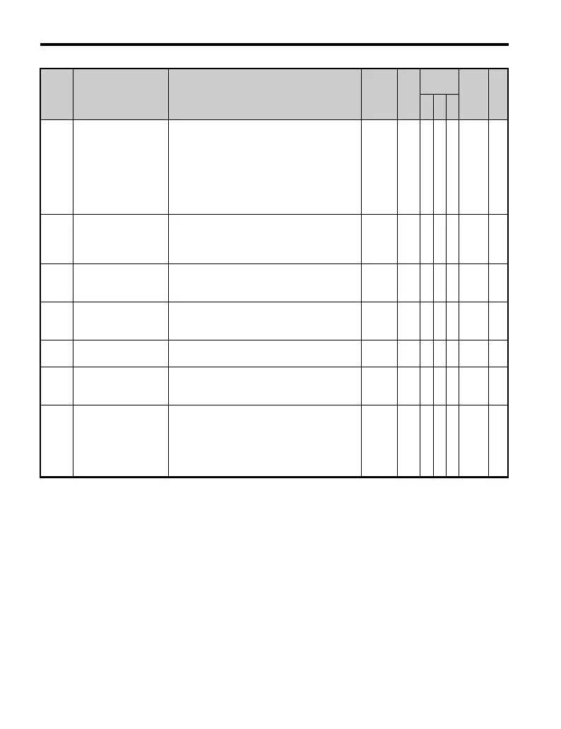
b5-20 PID Setpoint Scaling
Sets the units for b5-19, and for parameter
monitors U5-01 (PID Feedback) and U5-04
(PID Setpoint).
0: 0.01Hz units
1: 0.01% units
(100% of max output frequency)
2: r/min (check the number of motor poles)
3: User-set (set to b5-38 and b5-39)
0 to 3 1 A A A 1E2 —
b5-34
<22>
PID Output Lower
Limit
Sets the minimum output possible from the PID
controller. Set as a percentage (%) of the
maximum frequency. When set to 0.0%, lower
limit is disabled.
-100.0 to
+100.0
0.00
%
AAA 19F —
b5-35
<22>
PID Input Limit
Limits the input (error signal) to the PID
controller. Set as a percentage (%) of maximum
frequency. Acts as a bipolar limit.
0 to
1000.0
1000.
0%
AAA 1A0 —
b5-36
PID Feedback High
Detection Level
Sets the PID feedback high detection level as a
percentage (%) of the maximum frequency (E1-
04).
0 to 100
100
%
AAA 1A1 —
b5-37
PID Feedback High
Level Detection Time
Sets the PID feedback high level detection
delay time in seconds.
0.0 to
25.5
1.0 s A A A 1A2 —
b5-38
PID Setpoint / User
Display
0 to 60000: User-Set Display
Set the numbers displayed by designating the
maximum output frequency.
1 to
60000
<5> AAA 1FE —
b5-39
PID Setpoint and
Display Digits
Sets the number of digits for setting and
displaying the PID setpoint.
0: Integer
1: One decimal places
2: Two decimal places
3: Three decimal places
0 to 3
<5> AAA 1FF —
No. Name Description Range Def.
Control
Mode
Addr.
Hex
Pg.
V/f
O
LV
P
M

 Loading...


