B.2 Parameter Table
YASKAWA TM.V1000.01 V1000 Drive Installation & Start-Up Manual (Preliminary 01-19-07) 369
Parameter List
B
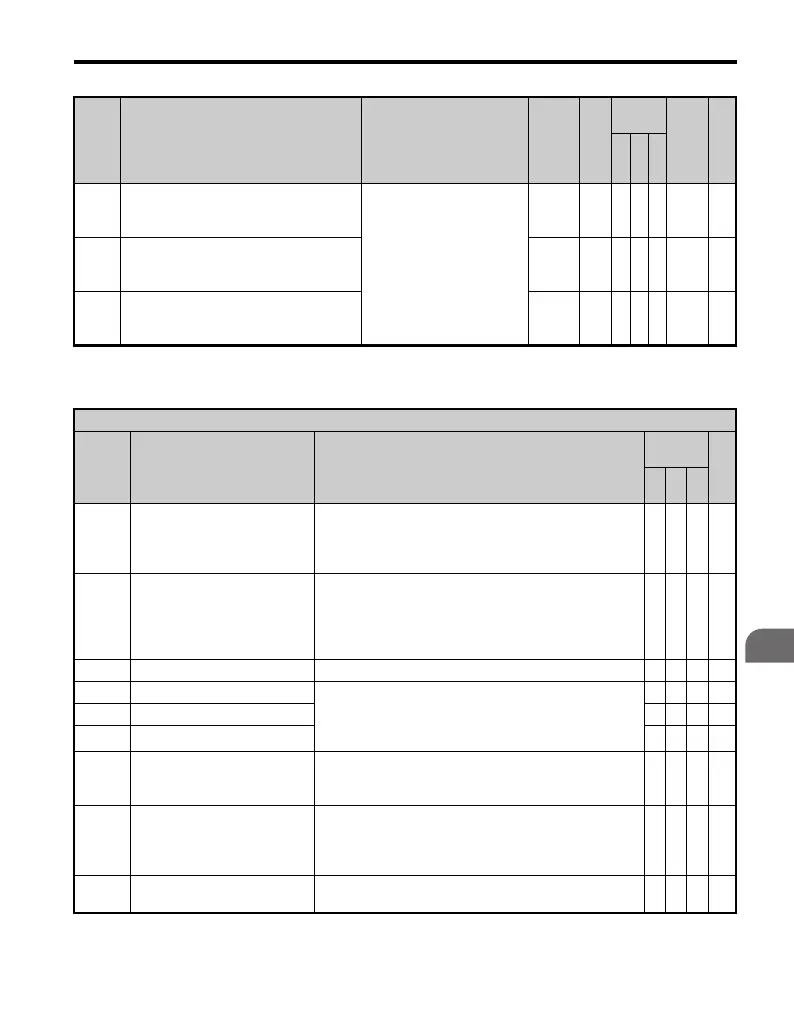
H1-05
Multi-Function Digital Input Terminal
S5 Function Selection
Refer to H1-01
0 to 9F
3(0)
<18
>
AAA 402 —
H1-06
Multi-Function Digital Input Terminal
S6 Function Selection
0 to 9F
4(3)
<18
>
A A A 403 —
H1-07
Multi-Function Digital Input Terminal
S7 Function Selection
0 to 9F
6(4)
<18
>
AAA 404 —
<18> Parenthetical value is the default when parameter A1-03 = 3330 3-Wire Initialization.
H1 Multi-Function Digital Input Selections
H1-
Setting
Function Description
Control
Mode
Pg.
V/
f
O
LV
P
M
0 3-Wire Sequence
Closed: Forward and reverse run commands are set up as
a 3-wire sequence.
The run and stop commands are automatically assigned
to terminals S1 and S2.
OOO—
1 Local/Remote Selection
Opening and closing the terminal causes the run
command to switch between the digital operator and a
remote source.
Open: Local
Closed: Remote
OOO—
2 Option/Drive Selection Closed: Option card O O O —
3 Multi-Step Speed Reference 1 When terminal A2 is set for auxiliary speed reference
signal of 0 to +10 V (H3-09 = 0), the values set to d1-01
through d1-16 can be selected using a combination of
Multi-Step Speed Reference Step 1 through 4.
OOO—
4 Multi-Step Speed Reference 2 O O O —
5 Multi-Step Speed Reference 3 O O O —
6 Jog Reference Selection
Closed: Inputs the Jog Frequency reference (d1-17).
Takes priority over other multi-step speed references
1 through 16
OOO—
7 Accel/Decel Time 1
Switch between parameters C1-01 through C1-04 based
on Accel/Decel Time Selection 1. Switching is also
possible between C1-05 through C1-08 by combining
this function with Accel/Decel Time Selection 2 (1A).
OOO—
8 Baseblock Command (N.O.)
Open: Normal operation
Closed: No drive output
OOO—
No. Name Description Range Def.
Control
Mode
Addr.
Hex
Pg.
V/
f
O
L
V
P
M

 Loading...


