B.2 Parameter Table
YASKAWA TM.V1000.01 V1000 Drive Installation & Start-Up Manual (Preliminary 01-19-07) 397
Parameter List
B
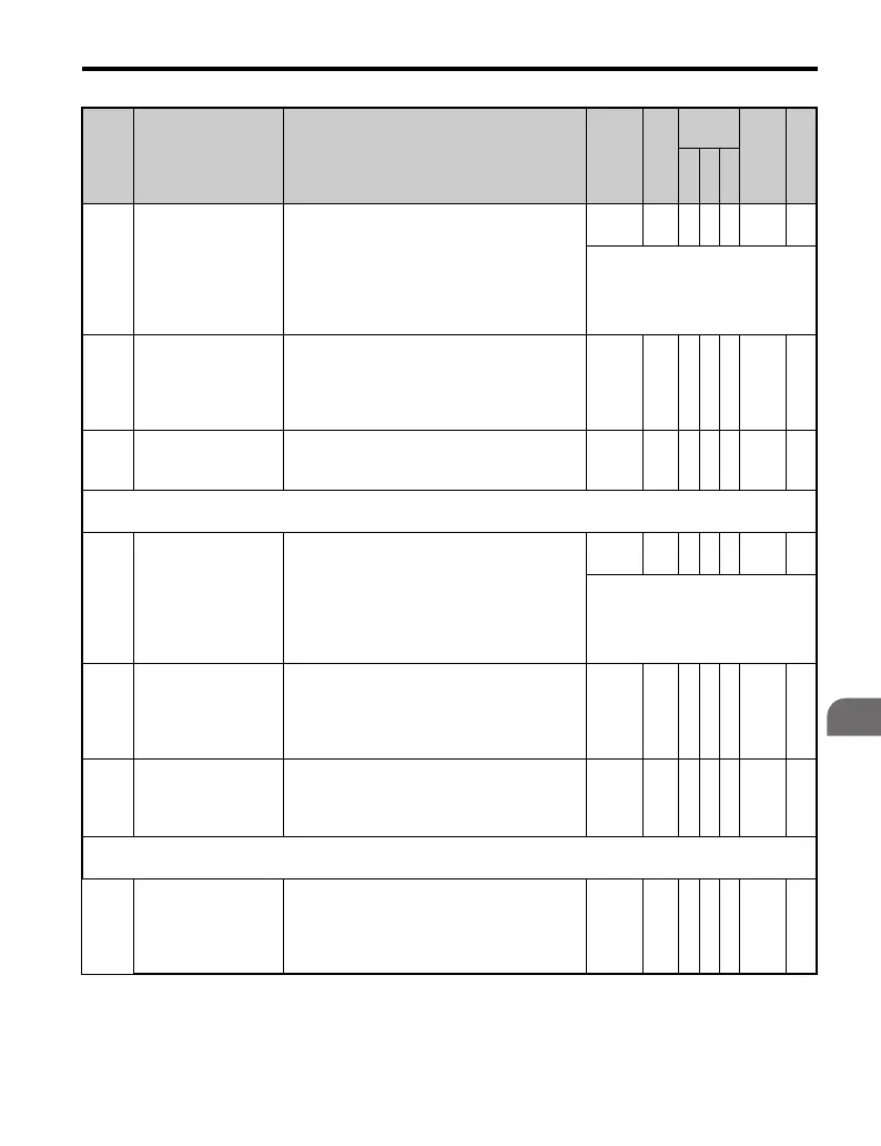
n1-02
Hunting Prevention
Gain Setting
Sets the gain for the Hunting Prevention
Function.
If the motor vibrates while lightly loaded and
n1-01 = 1, increase the gain by 0.1 until
vibration ceases.
If the motor stalls while n1-01 = 1, decrease
the gain by 0.1 until the stalling ceases.
0.00 to
2.50
1.00 A −− 581 —
If this setting is too high, then stall
prevention may result due to
excessive current suppression.
n1-03
Hunting Prevention
Time Constant
With Hunting Prevention, a derivative of the
output current is taken and the output voltage
is corrected in order to make the excitation
current a fixed value in V/f control. This will
also set a derivative of the time constant.
0 to 500
<12
>
A −− 582 —
n1-05
Hunting Prevention
Gain while in Reverse
Sets the gain for Hunting Prevention.
When set to 0, n1-02 is also enabled when the
drive is operating in reverse.
0.00 to
2.50
0.00 A −− 530 —
n2: Speed Feedback Detection Control Function
Use n2 parameters to configure the Speed Feedback Detection Control function operation.
n2-01
Speed Feedback
Detection Control
(AFR) Gain
Sets the internal speed feedback detection
control gain in the automatic frequency
regulator (AFR).
This parameter does not typically require
adjustment. Adjust this parameter as follows:
If hunting occurs, increase the set value.
If response is low, decrease the set value.
0.00 to
10.00
1.00 − A − 584 —
Adjust the setting by 0.05 units at a
time, while checking the response.
n2-02
Speed Feedback
Detection Control
(AFR) Time Constant
Sets the time constant to control the rate of
change in the speed feedback detection control.
Increase the setting if 0V occurs during sudden
load changes or the speed overshoots during
fast acceleration.
0 to
2000
50
ms
− A − 585 —
n2-03
Speed Feedback
Detection Control
(AFR) Time Constant
2
Sets the time constant to control the amount of
change in the speed at low speed.
0 to
2000
750
ms
− A − 586 —
n3: High-Slip Braking
Use n3 parameters to configure the high-slip braking function.
n3-01
High-Slip Braking
Deceleration
Frequency Width
Sets the aggressiveness output frequency
reduction as the drive stops the motor using
high-slip braking (HSB).
If Overvoltage (OV) faults occur during HSB,
this parameter may need to be increased.
1 to 20 5% A −− 588 —
No. Name Description Range Def.
Control
Mode
Addr.
Hex
Pg.
V/
f
O
L
V
P
M

 Loading...


