C.1 MEMOBUS/Modbus Basic Set-Up
430 YASKAWA TM.V1000.01 V1000 Drive Installation & Start-Up Manual (Preliminary 01-19-07)
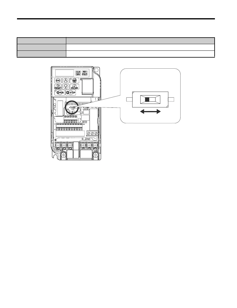
Table C.2 MEMOBUS/Modbus Switch Settings
Figure C.3
Figure C.3 MEMOBUS/Modbus Terminals and Terminal Resistor Switch
Note: 1. Separate the communication cables from the main circuit cables and control circuit wiring.
2. Use shielded cables for the communication cable, and use proper shield clamps. Shield at
one end only.
3. When using RS-485 communication, connect S+ to R+, and S- to R-, on the control circuit
terminal board. Refer to Figure C.4.
S2 Position Description
ON Internal terminal resistance ON
OFF Internal terminal resistance OFF (no terminal resistance); default setting
A – DIP switch S2 C – ON
B–OFF
BC
A

 Loading...


