3.8 I/O Connections
86 YASKAWA TM.V1000.01 V1000 Drive Installation & Start-Up Manual (Preliminary 01-19-07)
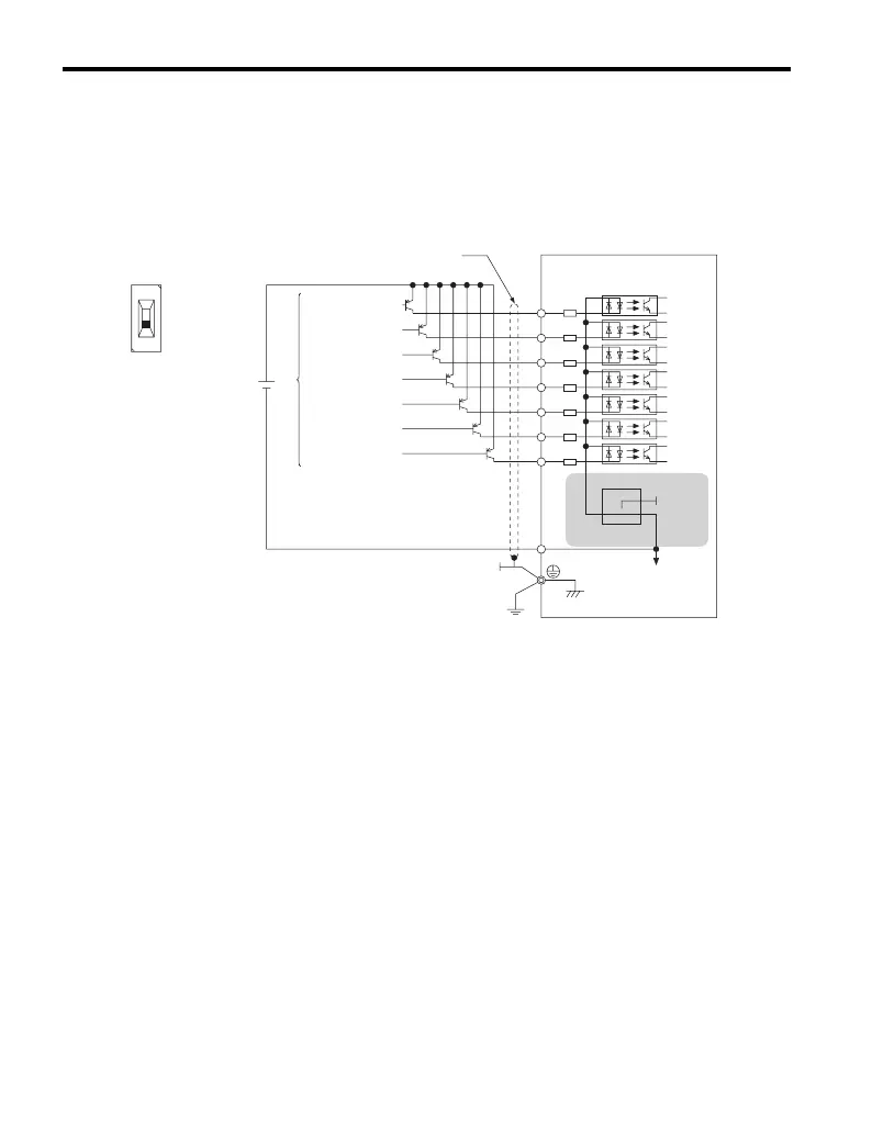
■ Transistor Input Signal Using +24 V Common/Source Mode
If the digital inputs shall be controlled by PNP transistors (+24 V common /
sourcing mode), set the DIP switch S3 to SOURCE. An external 24 V power
supply must be used.
Figure 3. 26
Figure 3.26 Source Mode: Sequence from PNP Transistor
(+24 V Common)
+24 V
Forward run / stop
Reverse run / stop
External fault N.O.
Fault rest
Multi-step speed 1
Multi-step speed 2
Jog frequency
External
power supply
Shielded cable
Drive
Multi-function input
S1
S2
S3
+24V
S4
S5
S6
S7
SC
S3
SINK
SOURCE
SINK
SOURCE

 Loading...


