Agilent 5DX Service Guide 5-31
5DX Series 3 Motion Control Assembly
Control at automatic startup. This is a single pulse only available at automatic
startup.
• Motion Controller Voltage Test Points - Provide the power signal for the
Motion Controller PCI 1 and 2. They should each be +5V.
• Backplane Voltage Test Points - Provides the power signal for the Backplane.
This should be +48V.
• Ground Test Points - Provide reference ground for signal or power
measurements.
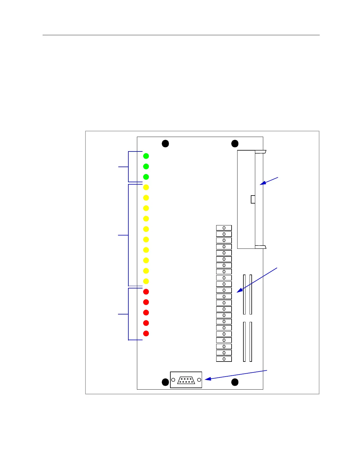
Figure 5-17: Motion Control Diagnostic Access Module
BACKPLANE +48V
MOTION CONTROLLER 1 +5V
MOTION CONTROLLER 2 +5V
Z FWD LIM
X FWD LIM
Y FWD LIM
X IN RANGE
Y IN RANGE
Y2 IN RANGE
R IN RANGE
X REV LIM
Y REV LIM
AWA HOME
X SERVO FAULT
Y1 SERVO FAULT
Y2 SERVO FAULT
R SERVO FAULT
CONTROLLER ABORT
R STEP
Y2 STEP
Y1 STEP
X STEP
AWA STEP
Z STEP
Y1 DIR
X DIR
AWA DIR
Z DIR
R ENC A
Y2 ENC A
Y1 ENC A
X ENC A
MRC KICKSTART
MRC I/O RESET
MOTION CONT 1+5V
MOTION CONT 2 +5V
BACKPLANE +48V
GND
GND
Status LEDs
Test Points
Service Key
Connector
Data Cable
Connector
Power LEDs
Fault LEDs
 Loading...

