Agilent 5DX Service Guide 5-35
5DX Series 3 Motion Control Assembly
Motor Relay Control
The Motor Relay Control is located on the Motor Relay Control/Stepper Board. It
is utilized by the Motion Enable Control which is discussed in the section entitled
Motion Controller PCI Cards on page 5-38.
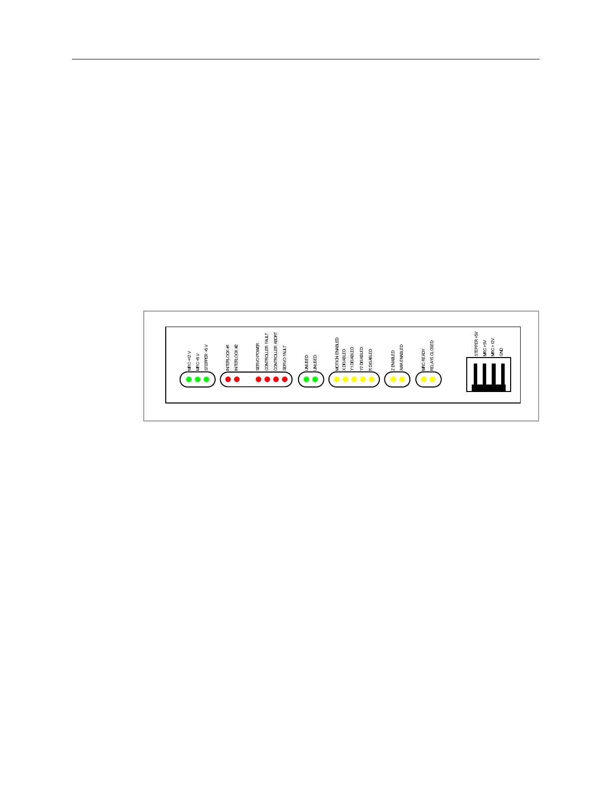
On the front edge of the Motor Relay Control/Stepper Board, the Motor Relay
Control supplies signals to several diagnostic LEDs. The LEDs represent the
components monitored by the Motor Relay Control. The LED colors symbolize:
• Red - off under normal conditions and indicating an unexpected state
• Yellow - varies, on or off under normal conditions indicating a controlled event
• Green - on under normal conditions indicating power is supplied
Figure 5-19: Diagnostic LEDs on the Motor Relay Control
0
5
&
9
0
5
&
9
6
7
(
3
3
(
5
9
,
1
7
(
5
/
2
&
.
,
1
7
(
5
/
2
&
.
6
(
5
9
2
3
2
:
(
5
&
2
1
7
5
2
/
/
(
5
)
$
8
/
7
6
(
5
9
2
)
$
8
/
7
&
2
1
7
5
2
/
/
(
5
$
%
2
5
7
0
2
7
,
2
1
(
1
$
%
/
(
'
;
'
,
6
$
%
/
(
'
<
'
,
6
$
%
/
(
'
<
'
,
6
$
%
/
(
'
5
'
,
6
$
%
/
(
'
=
(
1
$
%
/
(
'
$
:
$
(
1
$
%
/
(
'
0
5
&
5
(
$
'
<
5
(
/
$
<
6
&
/
2
6
(
'
6
7
(
3
3
(
5
9
0
5
&
9
0
5
&
9
*
1
'
8
1
8
6
(
'
8
1
8
6
(
'
 Loading...

