5-28 Panel Handling Subsystem
Motion Control Assembly 5DX Series 3
Motion Control Assembly
The Motion Control Assembly located in the Electronics Bay provides the controls
for moving the X-Axis, Y-Axis, Z-Axis, Rotary Axis, and provides the Auto Width
Adjustment of the rails in the XYZ Stage Assembly.
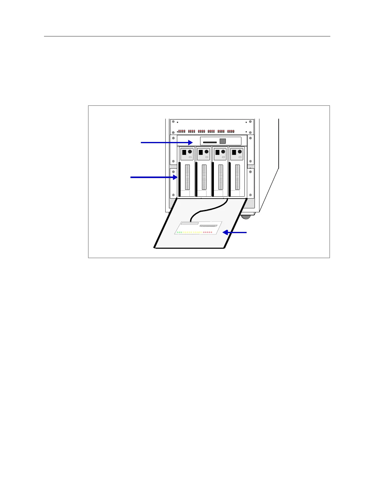
Figure 5-16: Motion Control Assembly
The Motion Control Assembly is shown in Figure 5-16 and is comprised of the
following components:
• Diagnostic Access Module — Provides test points for the various power
supply voltages and diagnostic light emitting diodes (LEDs) to indicate the
status of various signals.
• Servo Modules— Amplifies the signals required to operate the X-Axis, Y-
Axis and Rotary servomotors.
• Backplane — The interconnect point for the various components and power
for the Motion Control Assembly.
• Motor Relay Control/Stepper Module:
• Automatic Width Adjust (AWA) Stepper Driver — Controls the two
Automatic Width Adjust stepper motors.
• Z-Axis Stepper Driver — Controls the four Z-Axis stepper motors.
• Motor Relay Control— Provides the intelligence for the Motion Enable
Control. Includes a set of diagnostic LEDs to indicate the status of various
components controlled by the Motion Enable Control hardware.
Diagnostic
Access
Module
Motor Relay
Control/Stepper
Module
X, Y1, Y2, R
Servo
Modules
 Loading...

