3-10 Safety Interlock Subsystem
Safety Interlock Chains 5DX Series 3
Safety Interlock Chains
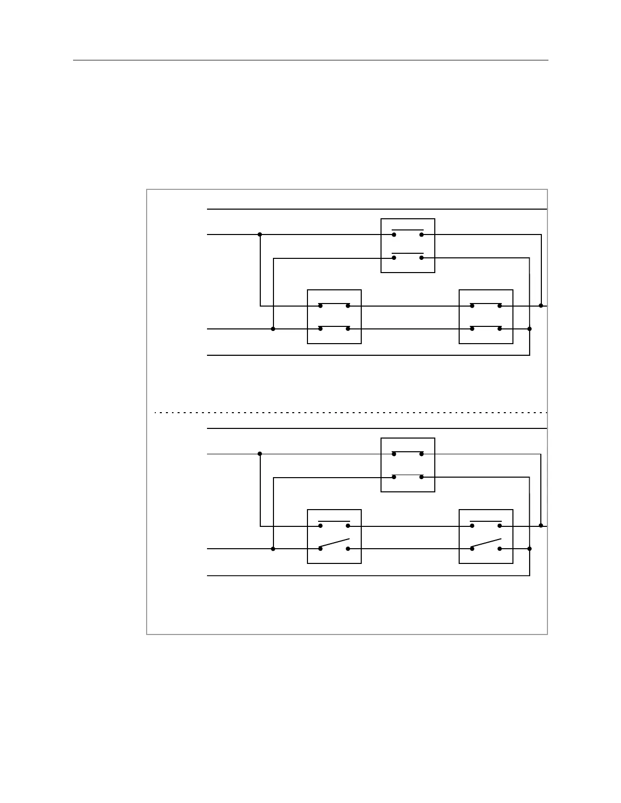
The Safety Interlock switches on the Inner Barrier and the Outer Barrier are in
parallel. This allows either Outer Barrier to be open when the Inner Barrier is
closed, or to have the Inner Barrier open when the Outer Barriers are closed.
Figure 3-8 shows how the Safety Interlocks are wired.
Figure 3-8: Safety Interlock Wiring Diagram
Chain #1
12 Volts
Chain #2
24 Volts
Inner Barrier
Left Outer Barrier Right Outer Barrier
Inner Configuration - Panel Inspection
Inner Barrier
Left Outer Barrier Right Outer Barrier
Outer Configuration - Panel Load/Unload
Chain #1
12 Volts
Chain #2
24 Volts
 Loading...

