Agilent 5DX Service Guide 3-9
5DX Series 3 Safety Interlock Switches
The outer barrier frame assembly is shown in Figure 3-6.
Figure 3-6: Safety Interlock Switch for the Outer Barrier Frame
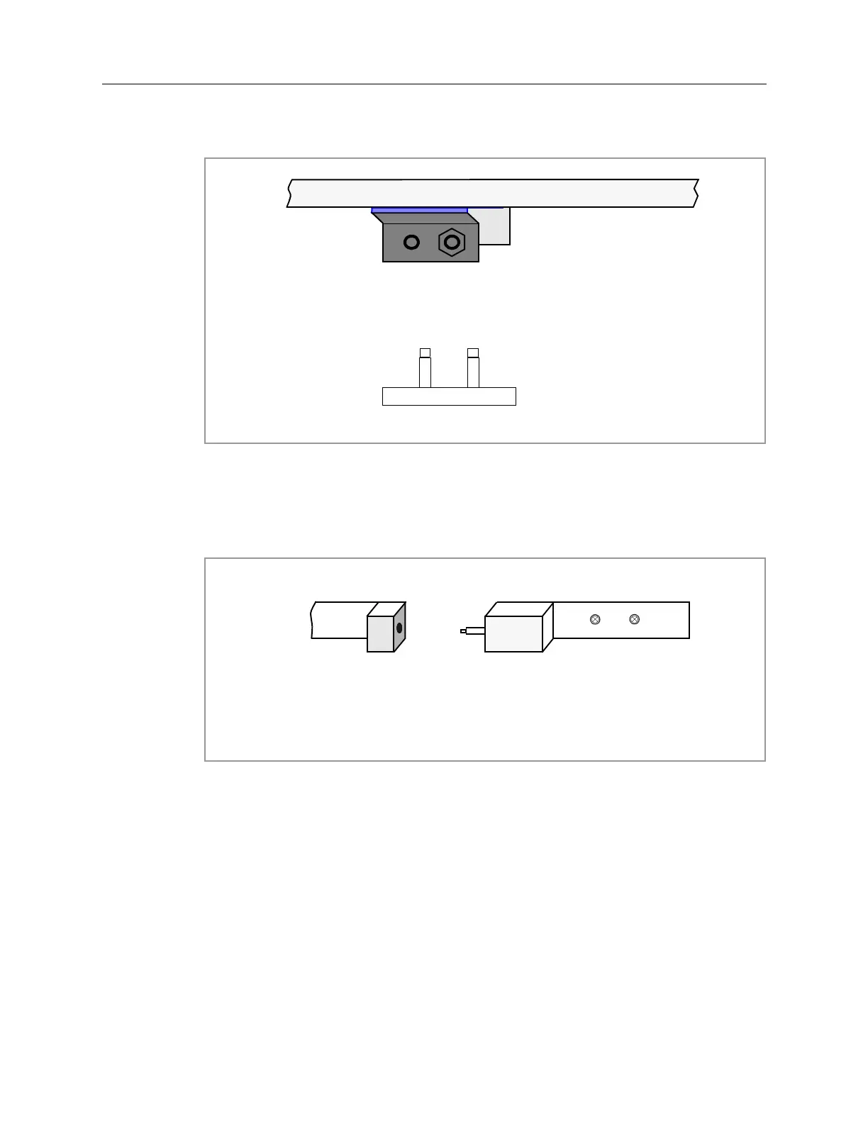
The interlocks for the inner barrier (shutter) assembly are shown in Figure 3-7.
This is as viewed from the front of the 5DX. The pins are on the right barrier half
in each case and the contact blocks are on the left.
Figure 3-7: Safety Interlock Switch for the Inner Barrier Frame
(Front View)
Contacts Inside Main Cabinet
Frame Pins
(Top Down View)
(Side View of Barrier halves)
Pin Block
Contact Block
 Loading...

