Agilent 5DX Service Guide 6-11
5DX Series 3 Pneumatic Subsystem Components
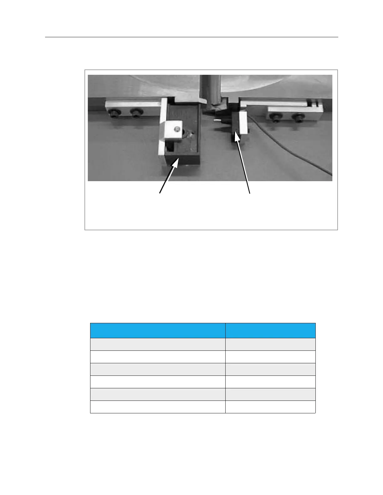
Figure 6-7: nner Barrier’s Safety Interlock
Barrier Operation
The pneumatics are controlled by signals through the Digital I/O Assembly. For
both the inner and outer barrier, status can be monitored by running the Hardware
Status and Control software and checking the input bits indicated in Table 6-1.
Table 6-1: Monitoring the Status or Input Bits
Input Bit Description Input Bit Number
Left Outer Barrier Closed 28
Left Panel-In-Place Switch Engaged 29
Right Outer Barrier Closed 32
Right Panel-In-Place Switch Engaged 34
Left Outer Barrier Open 41
Right Outer Barrier Open 42
Contact Block Pin Block
 Loading...

