Rockwell Automation Publication 193-UM015E-EN-P - October 2015 241
Operating Modes Chapter 5
• An operator station must be selected in Operator Station Type
(Parameter 224)
Or
• Option Match Warning must be enabled in WarningEnableC
(Paramete
r 192)
• Operator Station must be disabled in Mismatch Action
(Parameter 233)
• An
operator station must be selected in Operator Station Type
(Paramete
r 224)
7. Communication Fault & Idle Override (Parameter 346) must be enabled.
8. Network Fault Override (Parameter 347) must be enabled.
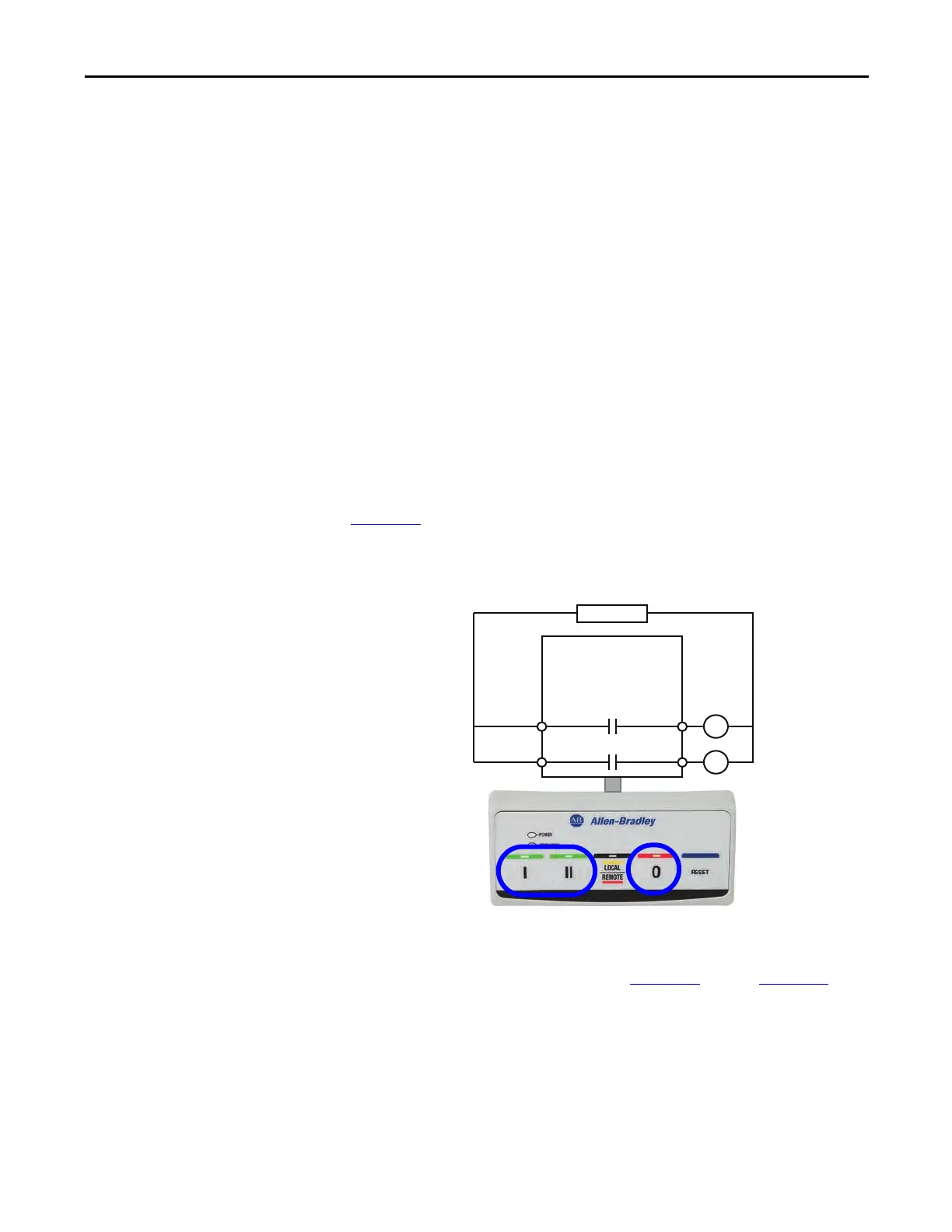
Wiring Diagram
The E300 relay’s Output Relay 0 and Output Relay 1 are wired as a control relays
in which the relay is controlled by the communication network or E300
Operator Station, and both output relays open when a trip event occurs.
Figure 146
is a wiring diagram of a reversing starter with Output Relay 0 and
Output Relay 1 configured as control relays.
Figure 146 - Reversing Starter (Network & Operator Station) Wiring Diagram
DeviceLogix Program
The DeviceLogix program that is shown in Figure 147 through Figure 150 is
automatically loaded and enabled in the E300 on power-up or when Operating
Mode (Parameter 195) is set to a value of 13.
R13 R14
Relay 1
Run Reverse
E300
Control Power
I- Run Forward
0- Stop
II- Run Reverse
R03 R04
Relay 0
Run Forward

 Loading...


