10. Card Cage
5
5
5
5
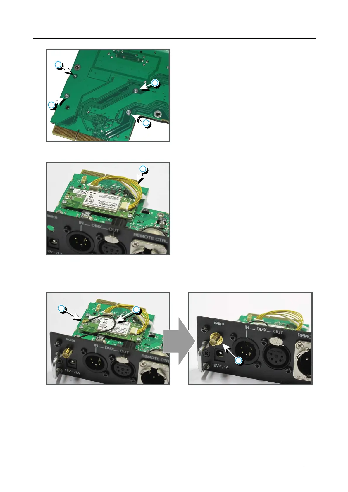
Image 10-11
6. Install the data wire (reference 6, image 10- 12) by plugging in the electrical connec tors.
6
Image 10-12
7. P osition the antenna (reference 7, image 10-13) in the hole on the front side of the Communication m odule.
8. P lug in the antenna wire connector (reference 8, image 10-13) on the W IF I module.
9. S ecure the antenna wire by installing the lock washer and nut (reference 9, im age 10-13).
8
9
7
Image 10-13
10.Install the antenna (reference 10, im age 10-14) by screwing it on its bas e.
R5905312 HDF W SERIES 24/01/2013
151

 Loading...


