10. Card Cage
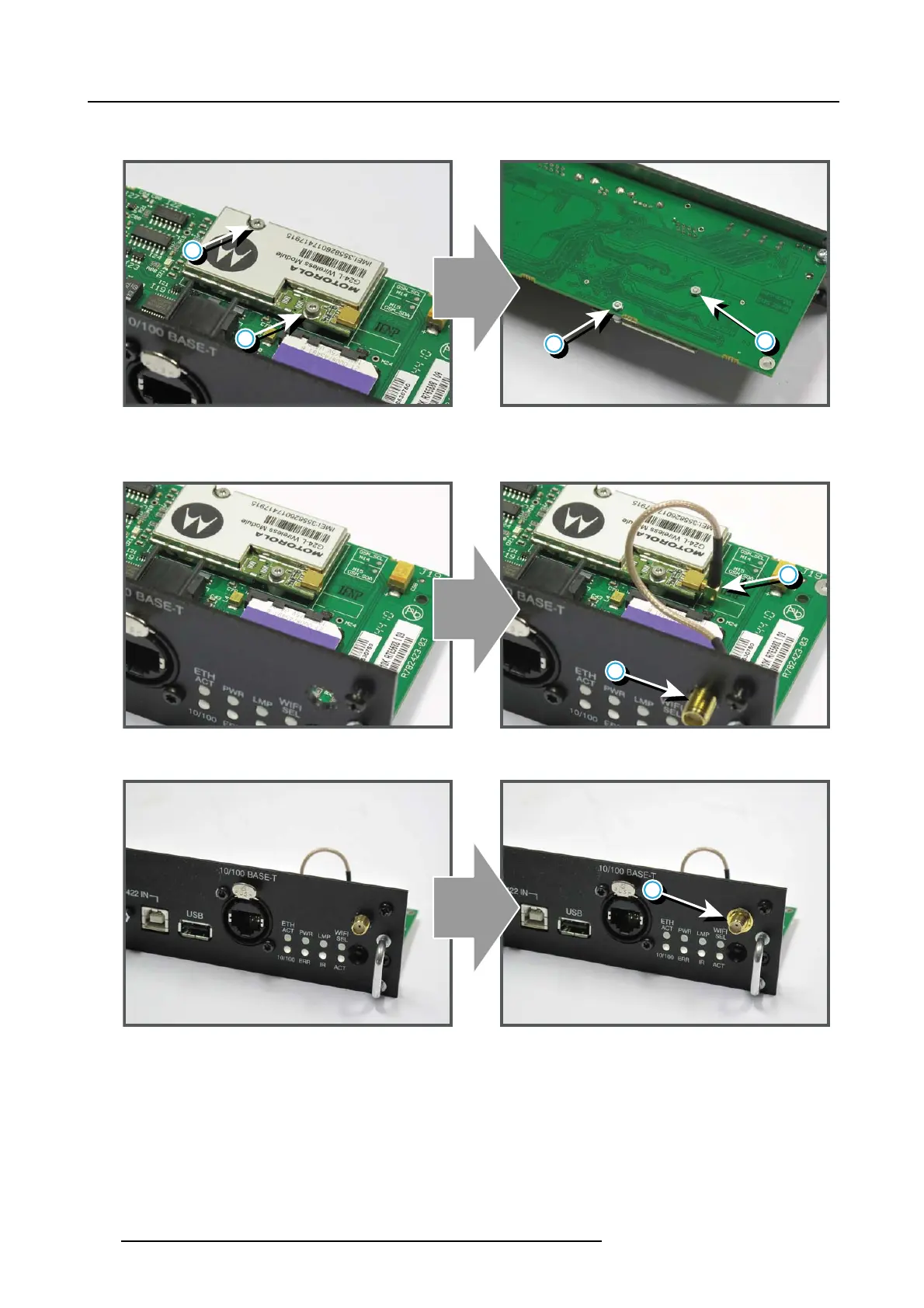
6. Install the screws (reference 5, image 10-18) and secure by tightening the nuts (reference 6, image 10-18) on the backside of
the Co mm unication board.
6
5
5
6
Image 10-18
7. P osition the antenna (reference 7, image 10-19) in the hole on the front side of the Communication m odule.
8. P lug in the antenna wire connector (reference 8, image 10-19) on the GSM module.
7
8
Image 10-19
9. S ecure the antenna wire by installing the
lock washer and nut (reference 9, image 10-20).
9
Image 10-20
10.Install the antenna (reference 10, im age 10-21) by screwing it on its bas e.
154
R5905312 HDF W SERIES 24/01/2013

 Loading...


