10. Card Cage
8
9
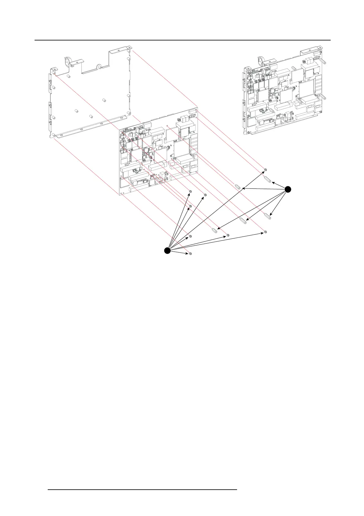
Image 10-26
8. R einstall the Deinterlacing module. See "Replacing the Deinterlacing module", page 160.
9. R einstall the Warp m odule. See "Replacing the Warp module", p age 159.
10.M ount the complete P MP board as semb ly back on the Input & Communication un it. Use a 2.5mm Allen wrench to fasten the 10
screws (reference 3 image 10-25) at the side and at the bottom as illustrated.
11.C onnect the gray flat cable (reference 1 image 10-23) and the red cable (reference 2 im age 10-24) from the LCD Display Interface
with the PMP board.
12.Install the top cov er of the Input & Communication unit. Use a 5.5m m nut driver to fasten the four nuts (reference 1 image 10-22)
andusea2.5mmAllenwrenchtofastenth
e eight screws a t the sides and the rear (reference 2 image 10-22).
13.Install the input board back in the Input & Communication unit. See "Installation of an input module", page 147.
158
R5905312 HDF W SERIES 24/01/2013

 Loading...


