10. Card Cage
2
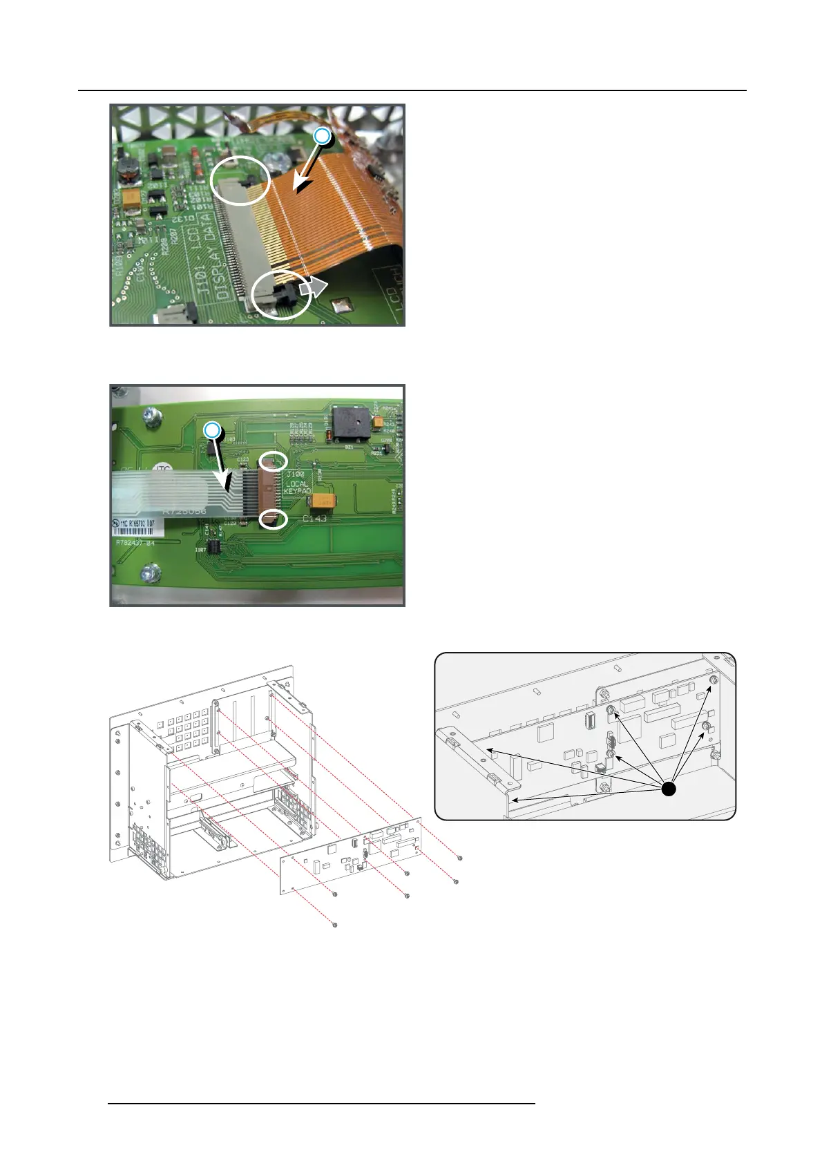
Image 10-31
5. D isconnect the flex cable (reference 3 image 10-32) of the Local Keypad from the LCD Display Interface. Unlock the latch of the
cable socket before pulling out the flex cable.
3
Image 10-32
6. R eplace the LCD Display Interface board. Use a T10 Torx driver to loos en/fasten the six screws (reference 1 image 10-33).
1
Image 10-33
7. C onnect the flex cable of the Local Key pad from the LCD Display Interface. O pen the latch of the cable sock et before inserting
the flex cable. Ensure to lock afterwards.
8. C onnect the two flex cables of the LCD Display from the LCD Display Interface boa rd. First insert the large flex and then the
small flex. Open the latch of the cable sockets before inserting the flex cables. Ensure t o lock afterwards.
9. C onnect the red cabl
e and gray cable with the LCD Display Interface.
10.Install the com plete PMP board a ssem bly bac k on the Input & Communication unit. S ee ser vice procedure "Replacing the PMP
board", page 15 6.
162
R5905312 HDF W SERIES 24/01/2013

 Loading...


