11. Lamp Power Supply
Image 11-9
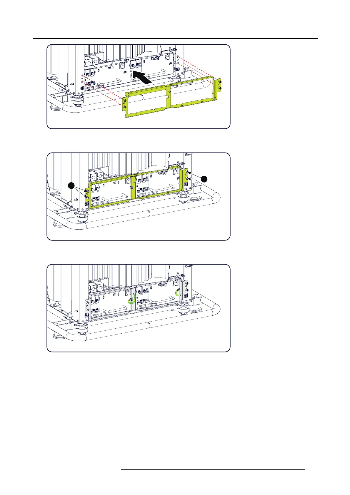
Mount fixation plate
4. S ecure the 4 s pring screws (1).
1
1
Image 11-10
Fixation screws
5. C onnect the grounding w ires mounted on the LPS fixation into the socket of each LPS unit.
Image 11-11
6. C onnect the power cables com ing from the SPG module with the LAMP OUT s ockets of the LPS module as illustrated. Insert at
the s ame time the connector coming from he second LP S unit. Fa sten the nuts with a torq ue of 4Nm (2.9 5 lbf*ft).
If it is the left LPS module, push the high pow er cables through the handle of t he this LP S module before connecting to the LAMP
OUT so c ke t .
Warning: Make sure to p lace the washers and cable eyes in correct order upon the pin as illustrated. Alwa ys use a plain
washer between the output pin and the cable eyes.
R5905312 HDF W SERIES 24/01/2013
175

 Loading...


