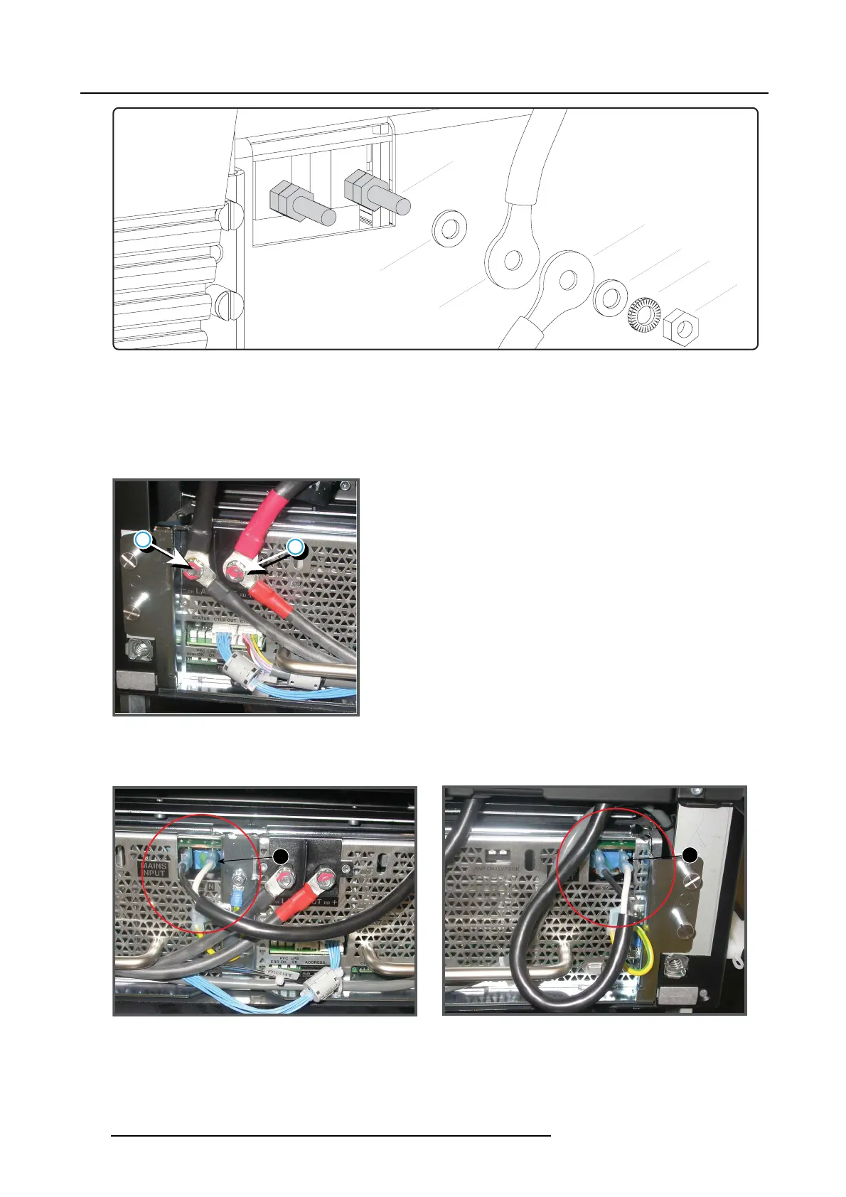
11. Lamp Power Supply
E2
L
N
P
W
E1
W
Image 11-12
Lamp out connection
P LPS output pin.
W Plain washer.
L Lock washer.
E1 Cable eye fr om SPG module.
E2 Cable eye from LPS unit.
NNut.
Warning: Respect the polarity of the socket and cables. Red marked c ables with the “ +” pin, black m arked cables with the “-”
pin.
+
-
Image 11-13
High power connection, left
7. C onnect the m ains input cables with the MAINS INPUT s ock ets of the new LPS module as illustrated.
Plug the connector o f the blue (or white) wire into the socket labeled with N.
N
N
Image 11-14
Mains input connection, left and right LPS module
176 R5905312 HDF W SERIES 24/01/2013

 Loading...


