11. Lamp Power Supply
When the left LPS module is replaced:
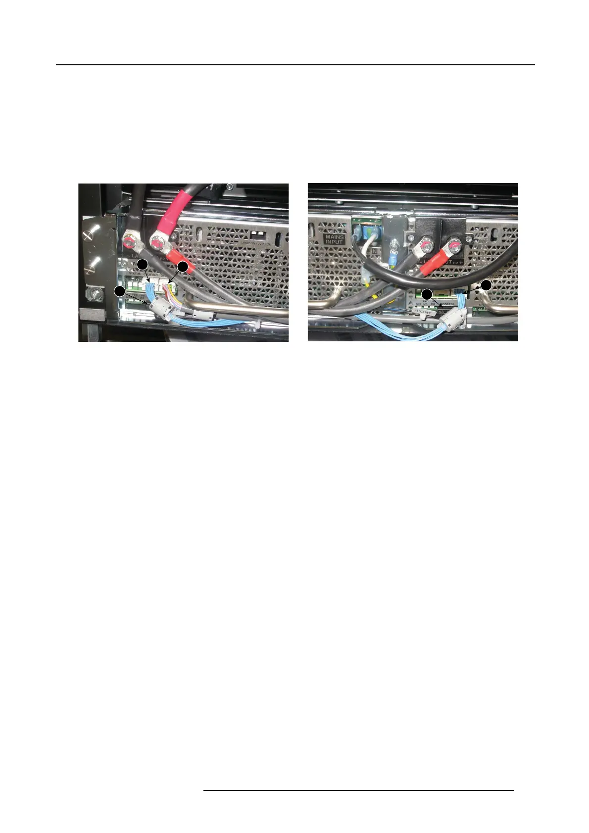
- Connect the wire unit com ing out of the projector with the CTLB IN so cket ( 1 ).
- Connect the CTLB OUT socket of the left LP S with the CTLB IN socket of the right LP S unit (2).
- Make the connection between the ADDRESS c onnector of the left LPS unit and the ADDRESS c onnector of the right LPS
unit (3). Make sure that the indication Le ft and Right is at the correct side.
When the right LPS mo dule is replaced:
- connect the wire unit coming from CTLB OUT socket of the left LPS with the CTLB IN socket (2)
- Make the connection between the ADDRESS c onnector of the left LPS unit and the ADDRESS c onnector of the right LPS
unit (3). Make sure that the indication Le ft and Right is at the correct side.
1
2
2
3
3
Image 11-15
Communication connections
R5905312 HDF W SERIES 24/01/2013 177

 Loading...


