15. Liquid cooling circuit
bacd
M
F
F
M
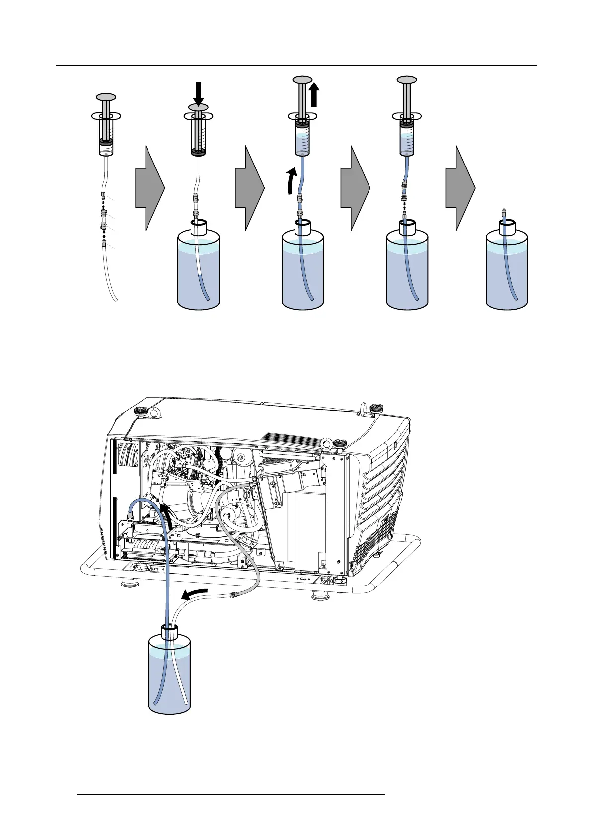
Image 15-21
Caution: It’s important that there is no air inside the tube. The pump is not self priming and hence is only capable of sucking
through small volumes of air.
3. P ush the male valv ed fitting of the filled tube into the fem ale valve d fitting at the heat exchanger. This is the entrance of the liquid
cooling circuit. M ake sure that the inlet of the filled tube
remains immersed.
4. C ouple the other plastic tube, which contains the female valved fitting, to the other side of the cooling circuit and immer ge the
tube end without fitting in the same bottle wherein the first tube is immersed. This is the exit of the liquid cooling circuit.
IN
OUT
Image 15-22
254 R5905312 HDF W SERIES 24/01/2013

 Loading...


