15. Liquid cooling circuit
Image 15-33
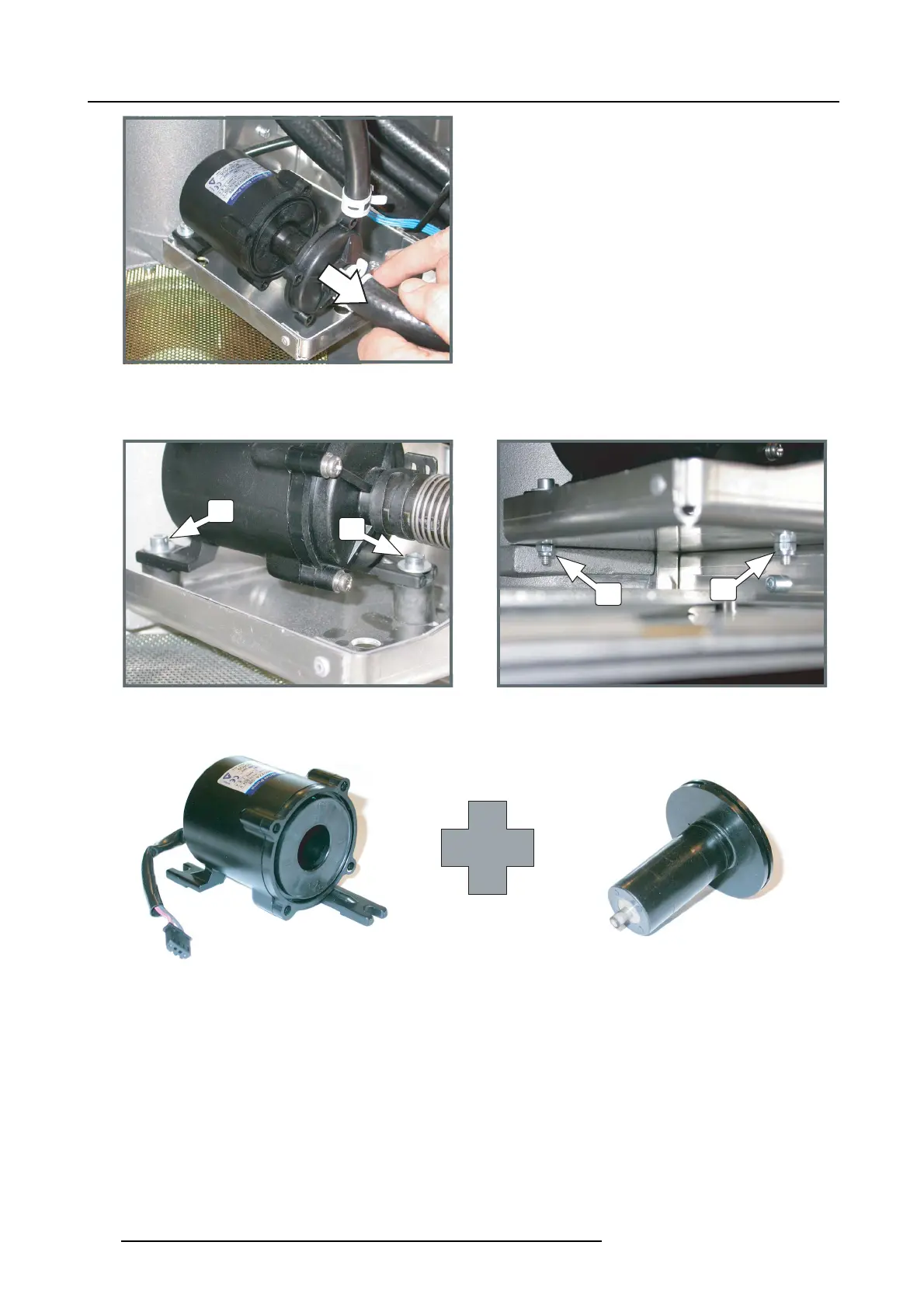
Pump house, remove
4. R elease the two hexagon socket head cap screws (reference 2) which fasten the pump motor to the seating of the pump . U se a
3 m m Allen wrench to release the s crews and a 7 mm open-end wrench to h old the nut ( reference 3) when releasing the screw.
2
2
3
3
Image 15-34
Pump, removal
5. R eplace the pump m oto r an d pum p rotor.
Image 15-35
Pump motor & rotor
6. Secur e the pump motor with two hexagon socket head cap screws (reference 2). Use a 3 mm A llen wrench to fasten the screws
anda7mmopen-end wrench to hold the nut (reference 3) while fasten the screw.
Caution: Make sure that the pump is m
ounted upon two rubber vibration rings (reference 4).
260
R5905312 HDF W SERIES 24/01/2013

 Loading...


